Sign In
Upload
Manuals
Brands
Scopus Manuals
Media Converter
IRD-2961
Scopus IRD-2961 Manuals
Manuals and User Guides for Scopus IRD-2961. We have
1
Scopus IRD-2961 manual available for free PDF download: User Manual
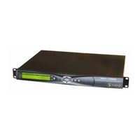
Scopus IRD-2961 User Manual (318 pages)
IRD-2900 Series Professional Integrated Receiver Decoders
Brand:
Scopus
| Category:
Media Converter
| Size: 8.95 MB
Table of Contents
T Echnical S Upport
8
Fcc Warning
10
Table of Contents
12
Chapter 1. Overview
21
General Information
21
Overview
21
Highlights and Benefits
22
Applications
23
Figure 1-1: Signal Path in the IRD-2900 - Functionality Block Diagram
24
Functionality
24
Figure 1-2: IRD-2900 Unit
25
Figure 1-3: Front View of the IRD
25
Front Panel
25
Mechanical Structure
25
Figure 1-4: IRD-2961 Rear Panel (IP Input Interface)
26
Figure 1-5: IRD-2961 Rear Panel (DVB-S Dual Input Interface)
26
Various Front-Ends
26
Figure 1-6: IRD-2961 Rear Panel (Decoder Only Interface)
27
Software Permission (Licensing)
27
Figure 1-7: IRD-2960 Rear Panel (Standard)
28
IRD-2900 Models
28
Figure 1-8: IRD-2961 Rear Panel
29
Figure 1-9: IRD-2962 Rear Panel
30
Figure 1-10: IRD-2963 Rear Panel
31
Figure 1-11: IRD-2980 Rear Panel
32
Figure 1-12: IRD-2981 Rear Panel
33
Figure 1-13: IRD-2990 Rear Panel
34
Figure 1-14: IRD-2991 Rear Panel
35
Figure 1-15: IRD-2992 Rear Panel
36
Local Management
37
Management
37
Remote Management
37
Characteristics and Specifications
38
Transport Stream Interface Options
38
Advanced Processing
41
Decoder Outputs
42
Conditional Access
45
Control and Monitoring
45
Compliance
46
Environmental Conditions
46
Physical and Power Specifications
47
Chapter 2. Installation
49
Installation
49
Installation Codes
49
Restricted Access Area
49
Safety Precautions
49
Site Preparation
50
Mechanical Rack Installation
51
Figure 2-1: Pair of Scopus Rack Slides
52
Figure 2-2: Scopus Rack Slide Measurement Specifications
53
Figure 2-3: Laying the Device on the Rack-Slides
54
Figure 2-4: Clipped Mounting Brackets
54
Figure 2-5: Device Mounted on a Pair of Rack-Slides
55
Figure 2-6: Multiple Devices Mounted on a Single Pair of Rack-Slides
56
Figure 2-7: DVB-CI Module
57
Insertion of the DVB-CI Module (PCMCIA)
57
Cable Connection
58
Figure 2-8: IRD-2992 Rear Panel
58
Figure 2-9: 9-Pin Male Connector Pin Numbering
59
Electrical Power Connection
62
Figure 2-10: Power Supply Configurations and Rack-Mount Grounding Jackscrew
62
Initialization and Configuration
62
Powering up
64
Tuning
64
Performing Serviceability Check
65
Chapter 3 IRD-2900 Control Interfaces
67
IRD-2900 Front Panel Screen Types
69
Figure 3-2: IRD-2900 Front Panel Menu (Root Menu) - Basic Structure
74
IRD-2900 Menu Tree
74
Front Panel Initialization Sequence
75
Figure 3-3: Web-Based Management Window - General View
77
Controls and Displays
78
Figure 3-5: Web-Based Management Title
79
Figure 3-6: Web-Based Management Menu and Sub-Menu Tabs
80
Figure 3-7: Status Menu
80
Control Elements
81
Figure 3-8: Main-Menu Tabs
81
Figure 3-9: Sub-Menu Tabs
81
Figure 3-10: Edit-Value Parameter
82
Figure 3-11: Select-Value Parameter
82
Figure 3-12: Refresh Button
83
Initializing the Web-Based Management
83
Figure 3-13: IP Address Field
84
Figure 3-14: IRD-2900 Web Management Access Box
85
Chapter 4 Operation and Management
87
Preset
87
Figure 4-1: Web Interface Preset Screen
88
Recall Preset
89
Figure 4-2: Web Interface Preset Recall Tab
90
Save Current Preset
90
Figure 4-3: Web Interface Save Preset Screen
91
Figure 4-4: Web Interface Save Tab
93
Figure 4-5: Web Interface - Save Preset as New Name Tab
94
Rename Preset
94
Figure 4-6: Web Interface Rename Preset Screen
95
Figure 4-7: Web Interface - Rename Preset Tab
95
Delete Preset
96
Figure 4-8: Web Interface Delete Preset Screen
97
Figure 4-9: Web Interface - Delete Preset Tab
97
Delete All Presets
98
Configuration
99
Figure 4-10: IRD-2900 Configuration Main Menu
99
Receiver Modules
100
Satellite Receiver Modules
101
Figure 4-11: DVB-S Receiver Parameters Menu Screen
102
Figure 4-12: DVB-S2 Receiver Parameters Menu Screen
111
Figure 4-13: DVB-DSNG Receiver Parameters Menu Screen
122
Figure 4-14: DVB-IP Receiver - Mpegoip 1 Parameters Menu Screen
131
Figure 4-15: DVB-IP Receiver - General Parameters Menu Screen
137
Figure 4-16: Stream Configuration Menu
141
Stream Configuration Menu
141
Figure 4-17: Stream Parameters Menu Screen
142
Filtering
148
Figure 4-19: General Filtering Parameters Menu Screen
150
Figure 4-20: Select Service Menu Screen
154
Figure 4-21: Select Pids Menu Screen
158
Figure 4-22: Service Configuration Menu
160
Service Configuration Menu
160
Figure 4-23: TV1 Menu Screen
163
Figure 4-24: Preferred Language Screen
167
Figure 4-25: PID Select Menu Screen
171
Figure 4-26: Port to Service Menu Screen
174
Figure 4-27: General Service Menu Screen
176
Video Configuration Menu
178
Figure 4-28: Video Configuration Menu
179
Figure 4-29: Video 1 Menu Screen
181
Figure 4-30: VBI 1 Parameters
188
Figure 4-31: OSD1 Menu Screen
198
Audio Configuration Menu
202
Figure 4-32: Audio Configuration Menu
202
Figure 4-33: Audio 1 Menu Screen
205
Data Configuration Menu
212
Figure 4-34: Data Configuration Menu
213
Figure 4-35: IP Data Port Menu Screen
218
Figure 4-36: Web Interface Genlock Screen
224
Genlock Configuration
224
Conditional Access Configuration Menu
226
Figure 4-37: Conditional Access Configuration Menu
226
Figure 4-38: Web Interface Conditional Access Screen
227
Figure 4-39: Web Interface Common Interface Screen
228
Figure 4-40: Web Interface BISS Screen
232
Figure 4-41: Unit Configuration Menu
235
Unit Configuration Menu
235
Figure 4-42: Web Interface - Unit Screen
236
Figure 4-43: Soft Reset Web-Interface Screen
238
Figure 4-44: Change Password Screen
238
Figure 4-45: Control Password Screen
239
Figure 4-47: Unit Ethernet Screen
243
Figure 4-48: IRD-2900 Licensing Screen
245
Figure 4-49: Alarms Web-Interface Screen
252
Figure 4-51: Web Interface - Traps Screen
254
Figure 4-52: Add New Trap Destination
256
Figure 4-53: Delete Trap Destination
256
Figure 4-54: Modify Trap Destination
256
Status
257
Receiver Status
258
Figure 4-56: IRD-2900 DVBS Status Screen
259
Figure 4-57: IRD-2900 DVBS2 Status Screen
261
Figure 4-58: IRD-2900 DVB IP Status Screen
262
Figure 4-59: IRD-2900 Stream Status Screen
264
Stream Status Menu
264
Figure 4-60: IRD-2900 Service Status Screen
267
Service Status
267
Video Status Menu
267
Figure 4-61: IRD-2900 Video Status Screen
268
Audio Status Menu
271
Figure 4-62: IRD-2900 Audio Status Screen
271
Data Status Menu
273
Figure 4-63: IRD-2900 IP Data Port Status Screen
274
Conditional Access Status Menu
275
Genlock Status
275
Figure 4-64: IRD-2900 Unit Status Screen
278
Unit Status Menu
278
Figure 4-65: Unit - Identity (Status Screen)
279
Figure 4-66: Unit - Versions (Status Screen)
279
Figure 4-67: Unit - Monitoring (Status Screen)
280
Figure 4-68: Web-Management: Licensing
282
Appendix A Software Download
283
Downloading Software Using FTP
283
Installation
283
Introduction
283
Figure A-1: Start Menu - Select Run
284
Figure A-2: Run Dialog Box
285
Figure A-3: Open FTP Session
285
Figure A-4: Login to FTP
286
Figure A-5: Access bin Folder
286
Figure A-6: Loading the File
287
PC Connection to the Serial Port
288
Opening Hyperterminal from MS Windows
289
PC Serial-COM (Terminal) Software
289
Defining the Communication
290
Figure A-7: Start Menu - Open Hyperterminal
290
Figure A-8: Hyperterminal - Enter Connection
291
Figure A-9: Select PC COM Port
291
Checking PC Terminal Communication with the IRD
292
Figure A-10: Port Settings Tab
292
Figure A-11: Hyperterminal Window
293
Installation
293
Figure A-12: Update Software Version Command
294
Figure A-13: Erasing Flash Process
295
Figure A-14: Ready to Receive New Software
296
Appendix Bip-Front End Software Upgrade Procedure
301
Appendix C Aspect Ratio Configuration Process
304
Table of Conversions
305
Appendix D Configuration File
311
Introduction
311
Parameters
311
Stream Configurations
311
Service Configurations
312
Video Configurations
313
Audio Configurations
314
Data Configurations
314
DVB S Receiver Configurations
314
IP Receiver Configuration
315
Appendix E Warning Messages
318
Warning Messages
318
Controls and Displays
67
Figure 3-1: Front Panel
67
Front Panel Control Interface
67
Advertisement
Advertisement
Related Products
Scopus IRD-2900 Series
Scopus IRD-2960
Scopus IRD-2962
Scopus IRD-2963
Scopus IRD-2980
Scopus IRD-2981
Scopus IRD-2990
Scopus IRD-2991
Scopus IRD-2992
Scopus CODICO IRD-2600
Scopus Categories
Media Converter
Switch
More Scopus Manuals
Login
Sign In
OR
Sign in with Facebook
Sign in with Google
Upload manual
Upload from disk
Upload from URL