Sign In
Upload
Manuals
Brands
Schweitzer Engineering Laboratories Manuals
Relays
SEL-587Z
Schweitzer Engineering Laboratories SEL-587Z Manuals
Manuals and User Guides for Schweitzer Engineering Laboratories SEL-587Z. We have
1
Schweitzer Engineering Laboratories SEL-587Z manual available for free PDF download: Instruction Manual
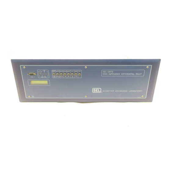
Schweitzer Engineering Laboratories SEL-587Z Instruction Manual (276 pages)
High-Impedance Differential Relay
Brand:
Schweitzer Engineering Laboratories
| Category:
Relays
| Size: 4.06 MB
Table of Contents
Table of Contents
3
List of Tables
5
List of Examples
11
Section 3: Relay Elements
11
Section 1: Introduction and Specifications
13
Introduction
13
Overview
14
Section 1: Introduction and Specifications
14
Figure 1.1 SEL-587Z Front Panel
14
Figure 1.2 SEL-587Z Hardware Block Diagram
15
Figure 1.3 Protection Functions
16
SEL-587Z Functions
16
Figure 1.4 Bus Protection (Simplified)
17
Figure 1.5 Transformer Protection (Simplified)
17
Specifications
19
Section 2: Installation
20
Section 2: Installation
21
Introduction
21
Relay Mounting and Maintenance
22
Figure 2.1 Relay Dimensions, Panel Cutout, and Drill Plan
23
Rear-Panel Connections
24
Figure 2.2 Relay Rear Panel
24
SEL-587Z Relay AC/DC Connection Diagrams
26
Section 2: Installation
26
Figure 2.3 Example AC Connection for High-Impedance Bus Protection
26
Figure 2.4 Example AC Connection with 50/51 Overcurrent Element
26
Figure 2.5 Example DC Connection
27
Circuit Board Jumpers and Battery
28
Table 2.1 Control Input Voltage Selection Jumper Positions
28
Figure 2.6 Input and Output Jumper Locations
29
Figure 2.7 Output Contact OUT4 Control Jumper Location
30
Table 2.2 Required Position of Jumper JMP13 for Desired Output Contact OUT4 Operation
30
Port Connector and Communications Cables
32
Section 3: Relay Elements
33
Introduction
33
High-Impedance Protection
34
Figure 3.1 Differential Relay Currents
34
Figure 3.2 A-Phase High-Impedance Element
34
Section 3: Relay Elements
35
Figure 3.3 B-Phase High-Impedance Element
35
Figure 3.4 C-Phase High-Impedance Element
35
Table 3.1 Differential Elements
35
Figure 3.5 Equivalent Circuit for through Fault
36
Figure 3.6 CT Characteristic
37
Equation 3.6
38
Figure 3.7 MOV Characteristic
39
Figure 3.8 Energy Dissipation Limits of the Movs (Maximum Four-Cycle Duration)
39
Figure 3.9 Single-Zone, Five Circuit Breaker Application (Simplified)
40
Figure 3.10 Overcurrent Elements in Differential Circuit (One Phase Shown)
41
Overcurrent Protection
42
Figure 3.11 Instantaneous Overcurrent Maximum Elements
43
Figure 3.12 Phase Overcurrent Elements
43
Figure 3.13 Negative-Sequence and Residual Overcurrent Elements
44
Figure 3.14 Inverse-Time Overcurrent (Max) Element
44
Figure 3.15 Inverse-Time Overcurrent (A-Phase) Element (B- and C-Phase Are Similar)
44
Figure 3.16 Transformer with Grounded-Wye-Connected Winding
46
Equation 3.8
48
Equation 3.11
49
Equation 3.20
50
Figure 3.17 U.S. Moderately Inverse Curve: U1
51
Figure 3.18 U.S. Inverse Curve: U2
52
Figure 3.19 U.S. very Inverse Curve: U3
53
Figure 3.20 U.S. Extremely Inverse Curve: U4
54
Figure 3.21 U.S. Short-Time Inverse Curve: U5
55
Figure 3.22 I.E.C. Class a Curve (Standard Inverse): C1
56
Figure 3.23 I.E.C. Class B Curve (very Inverse): C2
57
Figure 3.24 I.E.C. Class C Curve (Extremely Inverse): C3
58
Figure 3.25 I.E.C. Long-Time Inverse Curve: C4
59
Figure 3.26 I.E.C. Short-Time Inverse Curve: C5
60
Demand Ammetering
61
Figure 3.27 Response of Thermal Demand Ammeter to a Step Input (Setting DMTC = 15 Minutes)
62
Figure 3.28 Voltage V
62
Section 3: Relay Elements
63
Table 3.4 Transformer Detail
63
Example 3.1 Setting the Relay (Transformer)
63
Table 3.5 Temperature Parameters (IEEE C57.91: 1995)
64
Equation 3.32
65
Section 4: Control Logic
67
Introduction
67
Section 4: Control Logic
68
Optoisolated Inputs
68
Figure 4.1 Example Operation of Optoisolated Inputs IN1 and IN2
68
Figure 4.2 Breaker-And-A-Half Bus
69
Section 4: Control Logic
70
Example
70
Optoisolated Inputs
70
Example 4.4 Time Qualify Optoisolated Inputs
70
Section 4: Control Logic
71
Local Control Switches (Nlbn, Slbn, Clbn, Plbn)
71
Table 4.1 Control Switch Position, Label Settings, and Local Control Switch State
71
Figure 4.3 Local Control Switches Drive Local Bits LB1 through LB8
71
Table 4.2 Local Bit Functions
72
Table 4.3 Local Control Switch Types and Required Label Settings
72
Example 4.5 Configure LB2 to Replace the Supervisory Control Switch
72
Table 4.4 Local Bit LB3 Used as Bus Zone ON/OFF Switch
73
Example 4.6 Local Bit Controls Bus Protection
73
Remote Control Switches
75
Figure 4.4 Remote Control Switches Drive Remote Bits RB1 through RB8
75
SEL OGIC Control Equations
77
Table 4.6 SEL OGIC Control Equation Logic
78
Table 4.7 Processing Order of Relay Elements and Logic (Top to Bottom)
79
SEL OGIC Control Equation Variables/Timers
80
Example 4.7 Close Feed Pumps for Long Busbar Fault
80
Example 4.8 Transformer Settings Example
81
Trip Logic (Trn, Ultrn, TDURD)
82
Close Logic (CL, ULCL, 52A, CFD)
84
Example
85
Example 4.10 Close Logic SELOGIC Control Equation Settings
85
Output Contacts
86
Example 4.11 Default Settings
86
Rotating Display
89
Front-Panel Target Leds
90
Table 4.8 SEL-587Z Front-Panel Target LED Definitions
90
Section 5: Setting the Relay
91
Introduction
91
Section5: Setting the Relay
92
Settings Changes Via the Serial Port
92
Table 5.1 SET Command Editing Keystrokes
92
Settings Changes Via the Front Panel
93
Identifier and System Parameter Settings
94
SEL-587Z Settings Sheets
95
Figure 4.7 Trip Logic
100
Figure 4.8 Close Logic
100
Section 6: Serial Port Communications
107
Introduction
107
Section6: Serial Port Communications
108
Section6: Serial Port Communications
108
Port Connector and Communications Cables
108
Table 6.1 EIA-232 and EIA-485 Pinouts
108
Figure 6.1 9-Pin Serial Port Connector
108
Table 6.2 Serial Communications Port Pin Function Definitions
109
Figure 6.2 SEL-587Z to Computer
110
Figure 6.3 SEL-587Z to Modem
111
Communications Protocols
112
Table 6.3 Serial Port Automatic Messages
112
SEL Distributed Port Switch Protocol (LMD)
116
SEL Binary Protocols, Fast Meter, and Fast Operate
117
Table 6.4 Binary Message List
117
Table 6.5 ASCII Configuration Message List
117
Table 6.6 A5C0 Relay Definition Block
118
Table 6.7 A5C1 Fast Meter Configuration Block
118
Table 6.8 A5D1 Fast Meter Data Block
120
Table 6.9 A5C2/A5C3 Demand/Peakdemand Fast Meter Configuration Messages
120
Table 6.10 A5D2/A5D3 Demand/Peak Demand Fast Meter Message
121
Table 6.11 A5CE Fast Operate Configuration Block
121
Table 6.12 A5E0 Fast Operate Remote Bit Control
122
Table 6.13 A5E3 Fast Operate Breaker Control
123
Table 6.14 Communications Settings
125
Section 7: ASCII Command Reference
127
Introduction
127
Section7: ASCII Command Reference
128
Command Definitions
128
Table 7.1 ACC and 2AC Commands
128
Example 7.1 Access Level Attempt (Password Required)
128
Example 7.2 Access Level Attempt (Password Not Required)
129
Table 7.2 SEL-587Z Control Subcommands
133
Table 7.3 Password Requirements and Default Passwords
138
Table 7.4 SET Command Parameters
140
Section7: ASCII Command Reference
142
Table 7.5 Valid SHO Commands
142
Figure 7.1 SHO Command Sample Display
142
Figure 7.2 SHO L Command Sample Display
143
Figure 7.3 SHO P F Command Sample Display
143
Figure 7.4 SHO R Command Sample Display
143
Figure 7.5 SHO T Command Sample Display
144
Table 7.6 STA Command
145
Table 7.7 SEL-587Z Relay Word and Its Correspondence to TAR Command and Front-Panel Leds
146
SEL-587Z Relay Command Summary
148
Table 7.8 SEL-587Z Relay Commands
148
Table 7.9 SET/SHOW Command Options
148
Section 8: Front-Panel Interface
149
Introduction
149
Section8: Front-Panel Interface
150
Front-Panel Operation
150
Figure 8.1 Front-Panel User Interface
150
Figure 8.2 Front-Panel Pushbuttons-Primary Functions
153
Figure 8.3 Front-Panel Pushbuttons-Secondary Functions
154
Local Control
156
Figure 8.4 Local Control Switch Configured as an ON/OFF Switch
156
Figure 8.5 Local Control Switch Configured as an OFF/MOMENTARY Switch
156
Example 8.1 Display Points and Local Bit Configuration
156
Rotating Display
161
Section 9: Event Reports and SER
163
Introduction
163
Event Reports
164
Section 9: Event Reports and SER
165
Equation 9.1
165
Section 9: Event Reports and SER
166
Section 9: Event Reports and SER
166
Table 9.1 Event Types
166
Figure 9.1 Example Event Summary
166
Table 9.3 Event Report Current Columns
168
Table 9.4 Digital Element Columns
169
Table 9.2 Event Report
175
Figure 9.2 Example Event Report (1/4-Cycle Sample)
177
Equation 9.2
178
Sequential Events Recorder (SER) Report
179
Table 9.5 Accessing SER Report
180
Table 9.6 SER Report Additional Columns
181
Figure 9.3 Example Sequential Events Recorder (SER) Report
182
Section 10: Testing and Troubleshooting
183
Introduction
183
Testing Methods and Tools
184
Section 10: Testing and Troubleshooting
185
Figure 10.1 Low-Level Test Interface
185
Section 10: Testing and Troubleshooting
187
Acceptance Testing
187
Table 10.1 Acceptance Testing
187
Figure 10.2 Relay Part Number and Hardware Identification Sticker
188
Figure 10.3 STA Command
189
Figure 10.4 SHO Command
189
Figure 10.5 Test Connections for Balanced Load with Three-Phase Current Sources
191
Figure 10.6 Test Connections with Two-Phase Current Sources
191
Table 3.2 Instantaneous Overcurrent Elements
192
Table 10.2 Instantaneous Overcurrent Elements and Corresponding Settings/Relay Word Bits/Tar Commands
192
Section 10: Testing and Troubleshooting
193
Equation 10.1
193
Table 3.3 Inverse-Time Overcurrent Elements
194
Table 10.3 Inverse-Time Overcurrent Elements and Corresponding Settings/Relay Word Bits/Tar Commands
194
Equation 10.2
195
Table 10.4 Instantaneous Overcurrent Elements and Corresponding Settings/Relay Word Bits/Tar Commands
196
Figure 10.7 Test Connections for Three-Phase Voltage Sources
196
Commissioning Testing
197
Maintenance Testing
198
Table 10.5 Maintenance Testing
198
Relay Self-Tests
199
Table 10.6 Relay Self-Tests
199
Relay Troubleshooting
201
Relay Calibration
203
Factory Assistance
204
Appendix A: Firmware and Manual Versions
205
Appendix A: Firmware and Manual Versions
205
Firmware
205
Table A.1 Firmware Revision History
205
Instruction Manual
206
Table A.2 Instruction Manual Revision History
206
Appendix B: Firmware Upgrade Instructions
207
Appendixb: Firmware Upgrade Instructions
209
Figure B.1 Establishing a Connection
209
Figure B.2 Selecting the Computer Serial Port
209
Figure B.3 Determining Communications Parameters for the Computer
210
Figure B.4 Setting Terminal Emulation
210
Figure B.5 Terminal Emulation Startup Prompt
211
Figure B.6 Correcting Port Setting
211
Figure B.7 Correcting Communications Parameters
212
Figure B.8 Matching Computer to Relay Parameters
214
Figure B.9 Example Receive File Dialog Box
215
Figure B.10 Example Filename Identifying Old Firmware Version
215
Figure B.11 Downloading of Old Firmware
216
Figure B.12 Selecting the New Firmware to Send to the Relay
217
Figure B.13 Transferring New Firmware to the Relay
217
Appendixc: Relay Word Bits
221
Table C.1 SEL-587Z Relay Word Bit Summary
221
Appendix C: Relay Word Bits
222
Table C.2 Relay Word Bits: Overcurrent Elements
222
Table C.3 Relay Word Bits: High-Impedance Elements
223
Table C.4 Relay Word Bits: Local Bits
223
Table C.5 Relay Word Bits: Remote Bits
223
Table C.6 Relay Word Bits: SEL OGIC Control Equation Variables
224
Table C.7 Relay Word Bits: Trip/Close Logic
224
Table C.8 Relay Word Bits: Demand Elements
225
Table C.9 Relay Word Bits: Input and Output Contacts
225
Table C.10 Relay Word Bits: Miscellaneous
225
Table C.11 Alphabetic List of Relay Word Bits
225
Appendixd: Modbus RTU Communications Protocol
229
Table D.1 Modbus Query Fields
229
Appendix D: Modbus RTU Communications Protocol Modbus Overview
230
Table D.2 SEL-587Z Modbus Function Codes
230
Table D.3 SEL-587Z Modbus Exception Codes
230
Modbus Commands
232
Table D.4 01H Read Coil Status Command
232
Table D.5 02H Read Input Status Command
233
Table D.6 03H Read Holding Register Command
234
Table D.7 04H Read Holding Register Command
235
Table D.8 05H Force Single Coil Command
235
Table D.9 SEL-587Z Command Coils
236
Table D.10 06H Preset Single Register Command
237
Table D.11 07H Read Exception Status Command
237
Table D.12 08H Loopback Diagnostic Command
238
Table D.13 10H Preset Multiple Registers Command
239
Table D.14 64H Scattered Register Read Command
239
Table D.15 SEL-587Z Modbus Command Region
240
Table D.16 Modbus Command Codes
241
Table D.17 Assign Event Report Channel Using Address 00B2
243
Modbus Map
244
Table D.18 Modbus Map
244
Glossary
261
Index
271
SEL-587Z Relay Command Summary
275
Advertisement
Advertisement
Related Products
Schweitzer Engineering Laboratories SEL-501-2
Schweitzer Engineering Laboratories SEL-787
Schweitzer Engineering Laboratories SEL-2BFR-2
Schweitzer Engineering Laboratories SEL-700G Series
Schweitzer Engineering Laboratories SEL-267D
Schweitzer Engineering Laboratories SEL-221F-1
Schweitzer Engineering Laboratories SEL-167D
Schweitzer Engineering Laboratories SEL-321
Schweitzer Engineering Laboratories SEL-351S
Schweitzer Engineering Laboratories SEL-387-6
Schweitzer Engineering Laboratories Categories
Relays
Computer Hardware
Transceiver
Protection Device
Measuring Instruments
More Schweitzer Engineering Laboratories Manuals
Login
Sign In
OR
Sign in with Facebook
Sign in with Google
Upload manual
Upload from disk
Upload from URL