Sign In
Upload
Manuals
Brands
Saab Manuals
Automobile
V4
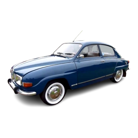
Saab V4 Manuals
Manuals and User Guides for Saab V4. We have
1
Saab V4 manual available for free PDF download: Service Manual
Saab V4 Service Manual (649 pages)
Brand:
Saab
| Category:
Automobile
| Size: 55.79 MB
Table of Contents
Contents
2
Chassis and Engine Numbers
8
General Data
10
Wrench Torques
23
Trouble Shooting
41
Starting Difficult, Cold Engine
41
Starting Difficult, Warm Engine
42
Engine Does Not Idle
42
Pinging
43
Ignition by Incandescence
43
Excessive Fuel Consumption
43
Lack of Power
44
Overheating
44
Engine Misses
44
Excessive Oil Consumption
45
Low Oil Pressure
46
Engine Jerks and Spits on Acceleration
46
Fuel Pump Operates Improperly or Not at All
47
Carburetor Hoods or Leaks Fuel
47
Uneven Idling
47
Faulty Fuel Gauge
47
Low Coolant Temperature
48
Battery Rundown
48
Brake Warning Light Glows
48
Tools Service Maintenance
49
General Hints
53
Special Tools
53
Thread System and Wrench Sizes
53
Tool Racks
53
Instructions for Jacking-Up the Car
54
Special Tools, Engine
55
Special Tools, Transmission
61
Special Tools, Chassis
65
Special Tools, Body
70
Special Tools, Miscellaneous
73
Service Inspections
75
Delivery Inspection
75
Guarantee Inspection
75
6.000 Miles Service
76
12.000 Miles Service
76
18.000 Miles Service
76
24.000 Miles Service
76
Supplementary Work
77
Order Work
77
Lubrication
78
Lubrication Chart
78
Drain Plugs, Oil
79
Electrical System
79
Filler and Level Plugs, Transmission
79
Chassis
80
Body
80
Lubrication Interval
82
Checking the Oil Level in the Gear Box
82
In Connection with Reconditioning
83
Rear Shock Absorbers, Saab 95
83
Other Lubrication
83
Laying up
83
Washing and Polishing
84
Waxing
84
Underbody Coating and Rust-Preventive Treatment
87
Touching-Up Underbody Coating
87
Rust-Preventing Treatment
87
Oil Pressure and Temperature
87
After the Treatment
88
Points of Rust Treatment
89
Engine Description
93
Cylinder Block
93
Cylinder Heads and Valves
93
Engine, Lefthand View
93
Crankshaft with Bearings
94
Camshaft and Tappets
94
Connecting Rods, Pistons and Piston Rings
94
Engine Righthand View
94
Lubrication System
95
Oil Pump, Relief Valve
95
Oil Pump Dismantled
95
Oil Filter
96
Ignition System
96
Fuel System
96
Fuel Tank as from Model 1971
97
Fuel Tank Ventilation
97
Exhaust Emission
97
Float
98
Choke Device with Rapid Idling
99
Idling System
99
Low-Speed System
100
High-Speed System
101
Econostat System
101
Acceleration System
101
Carburetor Fomoco
103
Starting Automatics
106
Automatic Choke
106
Carburetor Ford
110
Carburetor Exploded View
110
Float System
111
Choke
111
Main System
113
Deceleration System
115
Air Cleaner
116
Cooling System
117
Cooling Water Circulation
117
Crankcase Ventilation
118
Semi-Enclosed Crankcase Ventilation
118
Totally Enclosed Crankcase Ventilation
118
Removal of Engine
121
Removal of Engine Hood
121
Removal of Fastening Screws, Front Plate
121
Removal of Front Plate
121
Division of Removed Power Unit
124
Removal of Fuel Pump
124
Removal of Rocker Assembly
124
Removal of Thermostat
125
Removal of Water Pump
125
Removal of Tappets
125
Removal of Transmission Cover Oil Seal
125
Removal of Oil Filter
126
Removal of Oil Pump
126
Engine Block, Front View
126
Marking of Connecting Rods
126
Removal of Crankshaft Gear
127
Installation of Main Bearings
127
Removal of Balance Shaft
127
Installation of Crankshaft
127
Fitting of Pistons in Cylinder Bores
128
Torquing the Center Main Bearing Cap
128
Rear Crankshaft Seal Assembly
128
Measurement of Piston Clearance
128
Fltting of PISTON RINGS in CYLINDER BORES
129
Measurement of Piston Ring Gap
129
Fitting Piston Ring Gap
129
Piston Assembly
129
Installation of Balance Shaft
130
Installation of Balance Shaft Cover Plate
130
Installation of Flywheel
130
Installation of Crankshaft Gear
130
Axial Camshaft Bearing
131
Installation of Intermediate Plate
131
Installation Marks, Transmission Gear
131
Installation of Transmission Cover Oil Seal
132
Installation of Transmission Cover
132
Drive Shaft with Holder Ring
132
Installation of Oil Pan Gasket
132
Fitting the Two Bolts with Rubber Washers
133
Installation of Cylinder Head Gasket
133
Torquing of Cylinder Head Bolts
133
Installation of Rocker Assembly
133
Torquing of Induction Manifold
134
Installation of Oil Pressure Gauge
134
Cylinder Heads
135
Tightening Sequence, Cylinder Head Bolts
135
Installation of Induction Manifold Gasket
136
Tightening Sequence, Induction Manifold Bolts
136
Inspection of New Gasket in Valve Cover
136
Removal and Installation of Rocker Arm Assemblies
137
Disassembly and Reassembly of Rocker Arm Shaft
137
Replacement of Valve Stem Seals
138
Valve Grinding
138
Engine Installed in the Car
138
Removal of Valves
138
Milling the Valve Seat
139
Reaming of Valve Guide
139
Application of Pilot Arbor for Valve Milling Cutter
139
Valve Honing
139
Adjustment of Valves
140
Installation of Valves
140
Valve Numbering
140
Valve Adjustment
140
Checking the Compression Pressure
141
Removal and Installation of Valve Cover
141
Measuring Compression Pressure
141
Transmission Cover, Removal and Installation
142
Transmission Cover, Replacement of Balance Shaft Seal
142
Engine Removed
142
Replacement of Fan Bearing
143
Removal of Fan Bearing
143
Installation of Fan Bearing
143
Installation Position for Fan Pulley Flange
143
Removal and Installation of Transmission Gear
144
Removal and Installation of Camshaft
145
Measurement of Thrust Plate
146
Engine Body
151
Replacement of Crankshaft Seal
151
Mounting Position of the Crankshaft Seal
151
Installation of Sealing Keys
151
Crank Mechanism
152
Disassembly and Reassembly of Piston with Connecting Rod
152
Replacement of Disc-Shaft Bushing
152
Replacement of Ring Gear
152
Marking of Pistons and Connecting Rods
153
Piston with Connecting Rod
153
Torquing the Cylinder Head
155
Torquing the Induction Manifold
155
Removal and Installation of Piston Pins
156
Installation of New Gasket in Valve Cover
156
Checking the Connecting Rod
156
Rectangular Recess at the Piston Pin End
157
Position for Dolly
157
Connecting Rod Position at Install of Piston Pin
157
Inserting the Piston Pin
157
Crankshaft Bearing Inserts
158
Selecting Crankshaft Main Bearing/Connecting Rod Bearing Inserts
158
Measuring the Clearance
158
Instructions for the Use of Plastigage
158
Conicity of a Crankshaft Journal
159
Ovality of a Crankshaft Journal
159
Measuring Place for Plastigage
159
Measuring of Flat-Pressed Plastigage Strip
159
Oil Pan, Removal and Installation
160
Oil Pump, Removal and Installation
161
Overhauling the Oil Pump with a Repair Kit
162
Removal of Relief Valve Cover Plate
162
Oil Pump, Dismanted
162
Checking Axial Clearance of Rotor, Correct Clearance
162
Removal and Installation of Oil Filter Cartridge
163
Checking and Adjustment of Float Level
165
Idling Adjustment
165
Adjustment of Automatic Choke
165
Adjustment of Choke Flap
165
Adjustment of Thermostat Housing after Removal
166
Fast-Idling Adjustment
166
Carburetor
167
Location of Fitted Gasket
167
Removal of Thermostat Spring Housing Bolts
168
Ball and Weight, Accelerating Pump Fuel Channel
168
Location of Fitted Throttle Valve
168
Checking Location of Fitted Choke Plate
169
Checking the Accelerating Pump Setting
169
Setting of Float Chamber Valve
170
Setting of Automatic Choke
170
Fitting Thermostatic Spring
170
Location of Thermostatic Spring Housing
170
Setting the Choke Plate Vacuum Adjustment
171
Adjustment of Thermostatic Spring Lever Tongue
171
Vacuum Piston End Position
171
Checking the Setting
171
Setting of Choke Plate
172
Checking the Choke Plate Opening
172
Checking Position of Step Cam
172
Setting of the Mechanical Opening of the Choke Plate
173
Choke Plate Arm and Step Cam Stop
173
Checking Choke Plate Opening
173
Ford Carburetor
175
Removing the Carburetor
175
The Float Cover if Lifted off
175
Ball and Weight Is Removed
175
Fitting the Acceleration Pump Lever
176
Installing the Throttle Valve
176
Installing the Choke Valve
177
Ball and Weight Are Placed in the Acceleration Pump Passage
177
Float Level
177
Gauge for Measuring of Float Level
177
Adjusting the Acceleration Pump
178
Fast Idling, Checking and Adjusting
178
Checking the Setting of the Acceleration Pump
178
Checking Fast Idling Setting
178
Choke Valve Stop, Checking and Adjustment
179
Idling Adjustment, Engine Speed and CO-Value
179
Adjusting the Idling Setting
179
Removal of Deceleration Valve
179
Deceleration Valve with Bottom Cover Removed
180
Deceleration Valve
180
Deceleration Valve Top Cover Removed
180
Adjusting the Deceleration Valve
181
Air Cleaner Assembly
183
Checking Dismantled Valve Assembly
183
Thermostatically Controlled Air Preheater
183
Holding the Flap Valve in Position
184
The Flap Valve Has Moved to Its Central Position
184
The Flap Valve Has Moved to Its Left Position
184
Removal and Installation of Fuel Pump
185
Overhauling the Fuel Pump with a Repair Kit
185
Checking the Fuel Pump Pressure
186
Measuring Fuel Pressure
186
Fuel Tank
187
Fuel Line
187
Removal of Fuel Line
187
Installation of Fuel Line
187
Induction Manifold Removal and Installation
188
Front Muffler
189
Rear Muffler
189
Sealing between Mufflers and Exhaust Pipe
189
Exhaust Pipe
190
Rubber Cushions
190
Rubber Suspension Exhaust System
191
Radiator with Connections
193
Cooling and Heating System, Model 1969
194
Cooling and Heating System, Model 1970-1975
194
Cooling and Heating System as from Model 1976
195
Draining the Cooling System
196
Refilling the Cooling System
196
Cleaning the Cooling System
196
Pressure Testing the Cooling System for Leaks
196
Removal and Installation of Water Distribution Pipe
197
Replacement of Water Hoses
197
Removal and Installation of Water Pump
198
Overhauling the Water Pump with a Repair Kit
198
Insertion of Pump Bearing
199
Insertion of Pump Seal
199
Fitting of Impeller
199
Installation of Pulley
199
Replacing and Tensioning the Fan Belt
200
Thermostat, Removal and Installation
200
Inspection of Removed Thermostat
200
Service Engine
201
Exchange Engine
201
Electrical System Description
205
Battery
205
Generator
205
Starter
205
Wiring and Fuses
206
Brake Warning System
206
Warning Flasher
206
Battery Removal and Installation
207
Battery Maintenance
207
Electrolyte Level
207
Specific Gravity of Electrolyte
207
Cell Voltage
208
Battery Charging
208
Checking the Battery with a Cell Tester
208
Alternator up to an Incl. Chassis
209
Alternator
210
Internal Wiring
211
Terminal End of Alternator
211
Wiring Diagram for A.C. Alternator
212
Disassembly of Alternator for Renewal of Bearing
213
Reassembly of Alternator
213
Removal of Brush Holder Plate
213
Removal of Drive End Plate and Rotor
213
Renewal of Carbon Brushes
214
Soldering the Carbon Brushes Connectors
214
Mounting of the Alternator
214
Testing with Regulator
214
Testing the Components
215
Testing the Regulator Voltage at Half Exciter Current
215
Testing the Nominal Voltage Speed
215
Testing 2/3 of Maximum Output Current
215
Testing of Diodes with Ohm-Meter
216
Testing of Stator
216
Short Circuit of Windings
216
Generator Designation
218
Quick Checking of Alternator and Charging Regulator
220
Removal and Installation of Alternator
220
Adjustment of Fan Belt Tension
220
Assembling the Alternator
221
Pressing the Slip Ring Ball Bearing into Position
221
Pressing down the Brushes
221
Changing Brushes
222
Disconnecting the Brush Unit Assembly Wire
222
Unscrewing the Brush Unit Assembly
222
Removing the Brush Unit Assembly
223
Unsoldering the Brush Unit Terminals
223
Generator Testing
224
Testing Alternator on Bench
224
Excitation
225
Testing the R/Min at Maximum Output
225
Testing of Diodes
225
Removal and Installation of Starter
227
Disassembly of Starter
228
Removal of Locking Ring
228
Pressing down the Stop Ring
228
Removal and Installation of Solenoid Switch
229
Pressing up the Stop Ring
229
Changing the Carbon Brushes
230
Brush Holder Plate and Field Winding
230
Replacement of Starter Pinion
231
Removal and Installation of Ignition Coil
232
Ignition Coil Test
232
Distributor
233
Removal and Installation of Distributor
234
Marks for Ignition Setting
235
Removal of Distributor Gear
235
Ignition Governor
236
Disassembly of Distributor, as from Chassis
237
Changing of Breaker Points
238
Changing Breaker Points
239
Measuring Dwell Angle
240
Changing Capacitor
241
Changing Vacuum Chamber
241
Checking and Adjusting the Ignition Setting
241
Changing Distributor Cap
242
Testing Distributor in Test Bench
242
Distributor Settings When Testing in a Test Bench
242
Centrifugal and Vacuum Advance Distributor
243
Distributor with Double Acting Vacuum Control Unit
245
Ignition Setting
245
Changing Spark Plugs
246
Spark Plug Test
246
Interference Suppression at Radio Installation
247
Ignition Interference
247
Alternator Interference
247
Regulator Interference
247
Headlights
249
Alignment of Right-Dipping and Left-Dipping Asymmetric Lights
250
Alignment of Sealed Beam Units
251
Changing Headlight Bulbs
251
Changing the Sealed Beam Unit
251
Changing Headlight Insert
252
Headlights, Exploded View
252
Sealed Beam Unit
252
Aligning Right and Left Asymmetric Beams
253
Alignment by Means of Beam Aligning Apparatus
253
Correct Setting for Headlights
254
Incorrect Setting for Headlights
254
Screws for Adjusting Headlights up to and Incl. Model 1973
255
Screw for Adjusting Headlights as from Model 1974
255
Parking and Stop Lights
256
Flasher and Parking Light Front, Standard and Export Version
256
Tail Light
256
Changing Bulbs
257
Number-Plate Light
258
Interior Lighting
258
Direction Indicators
259
Direction Indicator Return Yoke
259
Horns
260
Signaling Device Model 1967
260
Signaling Device Models 1968 and 1969
260
Removal of Horn Button up to and Incl. Model 1967
260
Signaling Device Model 1970-1975
261
Signaling Device as from Model 1976
262
Removing the Guard and Horn Contact
262
Windshield Wiper
263
Wiper Motor
263
Windshield Wiper Motor, Lucas up to and Incl.
264
Wiper Mechanism
265
Windshield Washer
265
Headlight Cleaning Device
266
Electrical Connection and Operation
266
Electrical Connection and Operation as from Model 1972
267
Changing Wiper Blades
269
Removing the Protective Plate
269
Adjustment of Cord Length
269
Adjusting the Length of the Short Push-Rod
269
Electrical Controls and Switches
271
Special Switches
271
Lighting Relay
272
Town Light Relay
272
Changing the Oil - Pressure Switch
275
Changing the Electrical Temperature Transmitter
275
Warning Device for Forgotten Use of Seat Belt
275
Electrically Heated Rear Window
276
Wiring
277
Fuses
277
Fuse Block
277
Wiring Diagram
278
Key to Numbers
278
Repair, Connection of Accessories
366
Service Assembly
367
Uninsulated Cable Terminals
367
Wire Cutting
368
Wire Stripping
368
Crimping Procedure
368
Crimping Jaws
369
Clutch
377
Transmission
378
Synchromesh
379
Freewheel
380
Removal of Clutch
383
Installation of Clutch
383
Clutch Disc
385
Checking the Clutch and Changing Disc Facings
385
Clutch Operation
387
Removal and Installation of Clutch Pedal
387
Adjustment of Clutch-Pedal Free Movement
387
Master Cylinder
388
Slave Cylinder
389
Release Bearing
390
Bleeding the Master and Slave Cylinders
390
Removal of Engine and Gear Box
394
Gear-Shift Forks
398
Countershaft with Bearings and Gears
399
Primary Shaft with Bearings and Gears
400
Pinion Shaft with Bearings and Gears
400
Reassembly of Transmission Unit
402
Transmission Case and End Cover
407
Shimming
408
Measurement of Rear End Cover
408
Measurement of Rear End
408
Clutch Shaft
409
Changing the Sealing Ring
409
Changing the Clutch Shaft or Bearing
409
Reassembly, Clutch Shaft
410
Freewheel Hub
410
Disassembly of Freewheel Hub
411
Placing the Hub in the Tool
411
The Rollers Are Installed
411
Countershaft
412
Friction Brake
413
Friction Wheel
413
Primary Shaft
414
Synchromesh, Transmission
415
Synchronizer Rings
415
Synchronizing Force
415
Synchronizer Unit
415
Gear-Shift Mechanism
416
Removal of End Cover
416
Speedometer Drive Gear
418
Differential and Pinion-Ring Gear
419
Pinion Shaft and Ring Gear, General
419
Adjustment of Pinion
421
The Pinion End Face
421
Zeroing the Dial Indicator
422
Placing of Measuring Tool When Measuring
422
Remedys before Measuring
422
Adjustment of Pinion Shaft with Shims and Spacer
424
Removing Pinion Shaft Bearing with Puller
425
Driving in Pinion Shaft Thrust Bearing
425
Adjustment of Ring Gear Backlash
426
Checking the Measuring Tool
426
Marks of Ring Gear
426
Measuring Ring Gear Backlash
427
Replacement of Axial Bearing
428
Differential
429
Inner Universal Joint
431
Disassembly of Middle Shaft and Inner Universal Joint
431
Removal and Installation of Inner Drive Shaft
432
Removal of Sealing Ring Around Output Shaft
432
Replacement of Sealing Ring
432
Outer Universal Joint
433
Replacement of Broken Inner Driver
433
Tapping-Out Broken Inner Driver
433
Pressing out the Outer Drive Shaft
434
Placing the Lock Ring in Tool
435
Installation of Inner Drive Shaft
435
Brakes
437
Two-Circuit Brake System
439
Master Cylinder up to and Incl. Model 1970
440
Disc Brake
444
Rear Wheel Brakes and Handbrake
445
Vacuum Servo
446
Initial Position
446
Brake Position
446
Removal of Brake Drum for Inspection of Brake Lining
447
Inspection Hole in Brake Drum
447
Rear Brake Shoes
448
Fitting the Handbrake Lever
448
Rear
448
Adjustment of Brake Shoes
449
Replacement of Brake Linings
450
Centerless Grinding of Brake Linings
450
Brake Drums
451
Removal and Installation of Brake Drum
451
Wheel Puller
451
Machining Brake Drums
452
Replacement of Brake Disc
453
Disc Brake Components
453
Front Axle Unit with Disc Brake
454
Friction Pads, Disc Brake
455
Replacement of Friction Pads
455
Installation of Brake Pads
455
Hydraulic Footbrake System
457
Brake Fluid
457
Overhaul Instructions
457
Bleeding the Brake System
458
Location of Bleeding Nipples, Rear End
458
Location of Bleeding Nipple, Front End
458
Fitting the Piston Washer
462
Removal and Installation of Master Cylinder with Vacuum Servo
463
Removal and Installation of Master Cylinder
463
Overhaul of Master Cylinder
464
Removing the Lock Ring
464
Brake Lines and Fittings
469
Brake Hoses
469
Wheel Cylinders
470
Rear Wheel Cylindres, SAAB
470
Disc Brakes
471
Rear Wheel Cylinder
471
Attachment of Rear Wheel Cylinder
471
Screw Vise, Tool 786043
471
Reassembly of Brake Piston and Seals
472
Fitting the Wiper Seal
472
Replacement of Complete Brake Cylinder
473
Dismantling of Brake Body Assembly and Support Bracket
473
Brake Operation up to and Incl. Model 1968
474
Adjustment of Brake Pedal Clearance
474
Pedal Stand with Pendant Pedals
474
Brake Operation as from Model 1969
475
Removal of Contact Bracket
475
Removal of Cotter Pin
475
Handbrake Operation
476
Handbrake Cables
476
Removal of Handbrake Cable
476
Installation of Handbrake Cable
476
Handbrake Lever
477
Reverse Side of Rear, Left Backplate
477
Adjustment of Handbrake
478
Handbrake Lever and Adjusting Nuts
478
Front Axle and Suspension
481
Steering Knuckle
482
Front Axle Unit
482
Front Axle Assembly
483
Control Arms
484
Steering and Column Shift Gear
485
Steering and Gear Shift Mechanism
485
Wheel Alignment
486
Front-Wheel Alignment
487
Toe-In
487
Camber
488
Caster
488
King-Pin Inclination
489
Wheel Turning Angles
489
Wheel Alignment with Optical Measuring Equipment
490
Wheel Alignment Tables
491
Radial Tires
492
Rear-Wheel Alignment
493
Steering Knuckle and Ball Joints
494
Replacement of Front-Wheel Bearings
494
Removal of Inner Drive Shaft
495
Ball Joints
498
Disassembly of Front Coil Spring
498
Attachment of Steering Knuckle and Ball Joint
498
Replacement of Ball Joint Dust Excluders
499
Tightening of Control Arm Ball Joints
499
Removal of Control Arms and Steering Knuckle
500
Installation of Control Arms and Steering Knuckle
501
Replacement of Upper Control Arms
502
Upper and Lower Control Arms, Front Suspension
502
Replacement of Lower Control Arm
504
Checking Control Arms
504
Steering Wheel and Column Shift Gear
505
Steering Wheel and Steering Column Stand
505
Steering Wheel with Safety Pad
507
Padded Steering Wheels
509
The Safety Padding Is Removed
509
Removing the Steering Wheel Nut
509
Removal of Twist Stop
518
Adjustment of Twist Stop
518
Ignition Lock
519
Wire Picklock
519
Removing Lock Cylinder
519
Disassembly When Key Is Missing
520
Lock Cylinder and Gear-Lever Lock
520
Steering Gear
521
Installation of Steering Gear
522
Removal of Steering Gear
523
Pressure Spring and Piston Removed
523
Removal of Tie Rod End
523
Disassembly of Steering Gear
524
Reassembly of Steering, Gear, Previous Design
524
Disassembly of Steering Gear, New Design
525
Reassembly of Steering Gear, New Design
525
Inspection of Steering-Gear Components
526
Adjustment of Pinion Axial Play
526
Measuring the Shims
526
Measuring the Play
526
Adjustment of Rack Radial Play
527
Adjustment of Tie-Rod Inner Ball Joints
527
Inner Ball Joint
528
Removal of Outer Bearing Cup and Lock Nut
528
Replacement of Steering-Gear Dust Excluder
529
Tie-Rod Ends
530
Tie-Rod Assembly
530
Replacement of Rubber Seal
531
Suspension, Wheels
533
Front Suspension
535
Rear Suspension
536
Wheels
538
Hubs
538
Tires
538
Front Springs
539
Replacement of Coil Springs and Rubber Bumpers
539
Removal of Front Coil Spring with Tool No. 784082
539
Removal of Upper Ball Joint and Lower Spring Seat
540
Spring Compressor, Tool No. 784081 with and Without Spring
540
Rear Springs and Rubber Bumpers
543
Replacement of Stop Strap
543
Removal of Rear Axle
544
Installation of Rear Axle
544
Disconnecting the Rear-Axle Center Bearing Bracket
544
Center Bearing
545
Replacement of Rubber Bushings in Rear-Axle Center Bearing
545
Replacement of Bushing Without Removing the Rear Axle
545
Replacement of Bushing on a Removed Axle
545
Side Links
546
Replacement of Side-Link Rubber Bushings
546
Shock Absorbers
547
Front Shock Absorbers
547
Rear Shock Absorbers
548
Topping up Shock Absorbers
548
Stabilizer Bar
550
Replacement of Rubber Bushings on Stabilizer Bar
550
Adjusting and Repairing Wheels
551
Tire Maintenance
552
Front Wheel Hub
553
Rear Wheel Hub
554
Removal of Hub
555
Installation of Hub
555
Replacement of Ball Bearing in Rear Wheel Hub
556
Components of Rear Wheel Bearings
556
Body Assembly
561
Body Insulation
561
Body Fitments
563
Alignment Jig for Accident-Damaged Bodies
571
Alignment Jig
571
Tueing-Up Tool
571
Application of Trueing-Up Tool
572
Hoisting Gear
572
Description of Alignment Jig and Trueing-Up Tool
572
Removal of Damaged Body Panels
574
Welding New Body Panels
575
Sealing and Finishing
575
Repairs to Front End of Body
576
Front Cross-Member
576
Wheel House
577
Cutting Away the Wheel House and Control-Arm Bracket
577
Cutting the Wheel-House Flange by the Dash Panel
577
Floor Panel
580
Front Cross-Member and Engine Bracket
583
Other Operations
583
Repair of Body Sides
584
Side Panel Assy
584
Rear Pillar
585
Scuff Plate
585
Repair of Roof Assy
587
Fitting New Roof Rail and Moulding
588
Diagonal Measurement of Center Pillar
588
Repairs at Rear End of Body Assy
589
Checking Body Dimensions
589
Basic Body Measurements
590
Removal of Hood
591
Installation of Hood
591
Hood Lock
591
Front Plate up to and Incl. Model 1968
592
Headlamps Shells
592
Grille
592
Front Plate Model 1969-1970
593
Decor Frames, Headlights
593
Front Plate
593
Front Plate with Headlamp Wipers
594
Fenders
595
New Type of Left Rear Fender
596
Removal of Door
597
Removal and Installation of Window Regulator
597
Installation and Adjustment of Door
597
Replacement of Door Lock
598
Adjustment of Door Striker Plate
598
Replacement of Door Lock Cylinder
599
Spare Parts
599
Replacement of Lock Mechanism
600
Replacement of Luggage-Compartment Lock
600
Rear Door, SAAB 95
601
Adjustment of Balance Spring Tension
601
Changing the Latch, Door Lock
602
Changing Lock Cylinder in Outer Handle
602
Window-Glass
603
Replacement of Windshield
603
Removal of Windshield
603
Installation of Windshield
603
Replacement of Rear Window and Side Windows
604
Opening Side Windows
604
Replacement of Door Window
605
Removing the Hinge Retaining Screws
605
Trims and Interior Fitments
606
Headlining Saab 96
606
Door and Side Trims
606
Door Pillar Trim
606
Front Seats
609
Electric Heating of the Driver's Seat
609
Removal of Front Seats
609
Driver's Seat
609
Changing the Heating Pads
610
Changing the Thermostat
610
Rear Seat and Auxiliary Jump Seat Saab 95
611
Cleaning Upholstery
611
Specific Stains
611
Unidentified Stains
611
Cleaning Plasticized Fabrics
612
Instrument Panel
613
Replacement of Instrument Panel Overlay
613
Bumpers up to and Incl. Model 1975
614
Bumpers
615
Cleaning the Cellular Blocks
616
Changing the Cellular Blocks
616
Fitting the Bracking Strip
616
Body Finishing
617
Technical Data
618
Touch-Up and Refinish Instructions
618
Rubbing down
619
Equipment and Procedure for Refinishing
620
General Maintenance Work
620
Advertisement
Advertisement
Related Products
Saab 1981 900
Saab 1987 900
Saab 1989 900
Saab 1992 900
Saab 1995 900 Convertible
Saab 1996 NG900
Saab 2000 9-3
Saab 2000 9-5 2.3 Turbo Ecopower
Saab 2000 9-5 2.3t Ecopower
Saab 2000 9-5 3.0t Ecopower
Saab Categories
Automobile
Automobile Accessories
Car Navigation system
Automobile Electronics
Marine Radio
More Saab Manuals
Login
Sign In
OR
Sign in with Facebook
Sign in with Google
Upload manual
Upload from disk
Upload from URL