Sign In
Upload
Manuals
Brands
Rohde & Schwarz Manuals
Portable Generator
SMIQ03B
User Manuals: Rohde & Schwarz SMIQ03B Generator
Manuals and User Guides for Rohde & Schwarz SMIQ03B Generator. We have
3
Rohde & Schwarz SMIQ03B Generator manuals available for free PDF download: Operating Manual
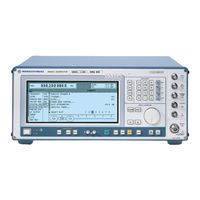
Rohde & Schwarz SMIQ03B Operating Manual (516 pages)
VECTOR SIGNAL GENERATOR
Brand:
Rohde & Schwarz
| Category:
Portable Generator
| Size: 4.48 MB
Table of Contents
Section 1
24
Table of Contents
24
Section 2
38
Preparation for Use
54
Putting into Operation
54
Supply Voltage
54
Switching On/Off the Instrument
54
Initial Status
55
RAM with Battery Back-Up
55
Setting Contrast and Brightness of the Display
55
Functional Test
56
Preset Setting
56
Fitting the Options
57
Opening the Casing
57
Fig. 1-1 SMIQ, View from the Top
58
Option SM-B1 - Reference Oscillator OCXO
58
Overview of the Slots
58
Option SM-B5 - FM/PM Modulator
59
Option SMIQB11 - Data Generator
60
Option SMIQB12 - Memory Extension to Data Generator
60
Option SMIQB14 - Fading Simulator FSIM1
61
Fig. 1-2 Module FSIM
62
Option SMIQB15 - Second Fading Simulator (FSIM2)
63
Option SMIQB17 - Noise Generator and Distortion Simulator
65
Fig. 1-3 Module NDSIM
66
Option SMIQB20 - Modulation Coder
66
Fig. 1-4 Module MCOD
67
Option SMIQB21 - Bit Error Rate Test
67
Other Software Options
68
Mounting into a 19" Rack
69
Option SMIQB19 - Rear Panel Connections for RF and LF
69
Display
70
Front and Rear Panel
70
Operation
70
Fig. 2-1 Front Panel View
71
Controls and Inputs/Outputs of the Front Panel
72
Fig. 2-2 Rear Panel View
81
Elements of the Rear Panel
82
Basic Operating Steps
91
Design of the Display
91
Fig. 2-3 Design of the Display
91
Calling the Menus
92
Fig. 2-4 MODULATION-AM Menu
92
Selection and Change of Parameters
93
Quick Selection of Menu (QUICK SELECT)
94
Triggering Action
94
Changing Unit of Level
95
ENTER] Key - Special Toggle Function
95
Use of [FREQ] and [LEVEL] Keys
95
Use of [RF ON/OFF] and [MOD ON/OFF] Keys
95
Correction of Input
96
Sample Setting for First Users
96
Fig. 2-5 Display after am Setting
98
Fig. 2-7 OPERATION Page of the MEM SEQ Menu
101
List Editor
101
Select and Generate - SELECT LIST
102
Deletion of Lists - DELETE LIST
103
Edition of Lists
104
Fig. 2-10 Edit Function EDIT/VIEW
104
Fig. 2-13 Edit Function DELETE: Input Window
108
Pattern Setting to Operate the List Editor
108
Save/Recall - Storing/Calling of Instrument Settings
112
Menu Summary
113
Fig. 2-16 Menu FREQUENCY (Preset Setting)
114
RF Frequency
114
Fig. 2-17 Example of a Circuit with Frequency Offset
115
Frequency Offset
115
Fig. 2-18 Menu LEVEL (Preset Setting) POWER RESOLUTION Is Set to 0.01 Db
116
RF Level
116
Fig. 2-19 Example of a Circuit with Level Offset
118
Level Offset
118
Interrupt-Free Level Setting
119
Switching On/Off Internal Level Control
119
Fig. 2-20 Menu LEVEL - ALC (Preset Setting)
120
Fig. 2-21 Menu LEVEL - UCOR - OPERATION Side
121
User Correction (UCOR)
121
Emf
122
Fig. 2-22 Menu UCOR - LEVEL-EDIT Side
122
Fig. 2-23 Menu LEVEL-EMF
122
Reset Overload Protection
123
RF on / OFF]-Key
123
Modulation - General
124
Modulation Sources
124
Table 2-1 Input Sockets for the Different Types of Modulation
124
Fig. 2-24 Example: Status Message "EXT1-LOW" in Case of Voltage at EXT1 too Low
125
Table 2-2 Status Messages in the Case of a Deviation from the Rated Value at the External Modulation Inputs EXT1 and EXT2
125
Fig. 2-25 Example: Settings of the LF Generator in the am Menu
126
LF Generator
126
Simultaneous Modulation
126
MOD ON/OFF] Key
127
Amplitude Modulation
128
Analog Modulations
128
Broadband am (BB-AM)
129
Fig. 2-27 Menu ANALOG MOD - BB-AM (Preset Setting)
129
Frequency Modulation
130
Fig. 2-29 Dependency of the FM Maximal Deviation on the RF Frequency Set
131
FM Deviation Limits
131
Preemphasis
131
Phase Modulation
132
Fig. 2-31 Dependency of the PM Maximal Deviation on the RF Frequency Set
133
PM Deviation Limits
133
Fig. 2-32 Menu MODULATION-PULSE (Preset Setting), Fitted with Option SM-B3, Pulse Modulator, and Option SM-B4, Pulse Generator
134
Pulse Modulation
134
Fig. 2-33 Example: Vector Modulation
135
Vector Modulation
135
Fig. 2-35 Effect of I/Q Impairment
138
I/Q Impairment
138
Table 2-3 Parameter Setting Ranges
138
Fading Simulation
139
Fig. 2-36 Fading Simulator in the SMIQ
139
Fig. 2-37 Two-Channel Fading
140
Output Power with Fading
140
Two-Channel Fading
140
Correlation between Paths
141
Fig. 2-38 Menu FADING SIM with Submenus
141
Menu FADING SIM
141
Menu STANDARD FADING
142
Fig. 2-41 Menu FINE DELAY
147
Menu FINE DELAY
147
Fig. 2-42 Two Paths with Menu MOVING DELAY
150
Fig. 2-43 Menu MOVING DELAY
150
Menu MOVING DELAY
150
Fig. 2-44 Example of Hop Sequence with BIRTH-DEATH Fading
152
Fig. 2-45 Menu BIRTH-DEATH
152
Menu BIRTH-DEATH
152
Test Procedure
154
Digital Modulation
155
Digital Modulation Methods and Coding
156
PSK and QAM Modulation
156
Modulation Π/4Dqpsk
157
Table 2-4 Phase Shifts for /4DQPSK Without Coding
157
Table 2-4 Phase Shifts for Π
157
Table 2-5 Phase Shifts for /4DQPSK with Coding NADC, PDC, PHS, TETRA or APCO25
157
Table 2-5 Phase Shifts for Π
157
Table 2-6 Phase Shifts for /4DQPSK with Coding TFTS
157
Table 2-6 Phase Shifts for Π
157
Coding
158
FSK Modulation
158
Table 2-7 Frequency Deviations for FSK Methods
158
Table 2-8 Possible Combination of Modulation Method and Coding
158
Table 2-9 Coding Algorithms
159
Setting Conflicts
160
Table 2-10 Examples of Settings Conflicts
160
Internal Modulation Data and Control Signals from Lists
161
Internal PRBS Data and Pattern
163
Table 2-11 PRBS Generators of Modulation Coder
163
Digital Data and Clock Output Signals
164
External Modulation Data and Control Signals
164
Parallel Interfaces DATA and SYMBOL CLOCK
164
Serial Interfaces DATA, BIT CLOCK and SYMBOL CLOCK
164
External Serial Modulation Data
165
External Parallel Modulation Data
166
Asynchronous Interface for External Modulation Data
167
External Control Signals
167
Envelope Control
168
Table 2-12 Logic Function of Signals BURST GATE and LEVEL ATT
168
Clock Signals
169
RF Level for Digital Modulation
169
Digital Modulation Menu
170
Digital Standard PHS
184
Sync and Trigger Signals
185
PN Generators as Internal Data Source
186
Table 2-13 PRBS Generators for PHS
186
External Modulation Data
187
Lists as Internal Data Source
187
Menu DIGITAL STANDARD - PHS
188
Digital Standard IS-95 CDMA
199
Table 2-14 CDMA: Channel Numbers and Their Frequencies
201
Table 2-15 Preferred CDMA-Frequency Channels According to J-STD-008
201
Sync and Trigger Signals
202
PRBS Data Source in Forward Link
203
PN Generators as Internal Data Source for Reverse Link
204
Table 2-16 PN Generators for IS-95 Reverse Link
204
Menu IS-95 CDMA Standard - Forward Link Signal
205
Menu IS-95 CDMA Standard - Reverse Link Signal Without Channel Coding
215
Menu IS-95 CDMA Standard - Reverse Link Signal with Channel Coding
217
Digital Standard W-CDMA (NTT Docomo/Arib 0.0)
219
Sync and Trigger Signals
221
PN Generators as Internal Data Source
222
Table 2-17 PN Generators for W-CDMA
222
Lists as an Internal Data Source
223
Menu W-CDMA Standard - Downlink and Uplink Signals Without IQ Multiplex
223
Menu W-CDMA Standard - Uplink Signals with IQ Multiplex
234
Description of Mobile Radio Transmission Method 3GPP W-CDMA
238
Digital Standard 3GPP W-CDMA (FDD)
238
Table 2-18 Parameters of W-CDMA System
239
System Components
240
Table 2-19 Generator Polynomials of Uplink Long Scrambling Code Generators
241
Table 2-20 Generator Polynomials of Uplink Short Scrambling Code Generators
242
Table 2-21 Mapping of the Quaternary Output Sequence into the Binary IQ Level
242
Table 2-22 Hierarchical Structure of 3GPP W-CDMA Frames
244
Generation of 3GPP W-CDMA Signals
246
Menu WCDMA/3GPP
248
WCDMA/3GPP Menu - Para. Predef. Submenu
258
WCDMA/3GPP Menu - Display of CCDF
260
WCDMA/3GPP Menu - Displaying Constellation Diagrams
261
WCDMA/3GPP Menu - BS Configuration Submenu
262
WCDMA/3GPP Menu - MS Configuration Submenu
268
Table 2-23 Structure of the DPDCH Channel Table Depending on the Overall Symbol Rate
276
WCDMA/3GPP - Multi Channel Edit Menu
277
WCDMA/3GPP - Display of Channel Graph Menu
279
WCDMA/3GPP Menu - Display of Code Domain and Code Domain Conflicts
280
2.14.2.10 Effect of CLIPPING LEVEL Parameter on Signal
282
Table 2-24 Change of Crest Factor in the Case of Clipping
283
2.14.2.11 Synchronization and Trigger Signals
284
2.14.2.12 Preset/Default Values
285
Table 2-25 Default Values for Base Station Parameters
285
Table 2-26 Default Values for Mobile Station Parameters
287
3GPP W-CDMA Signals in Time Domain
288
Background Information for the Generation of 3GPP W-CDMA Signals
288
3GPP W-CDMA Signals in the Frequency Range
294
Effect of Data Source on the 3GPP W-CDMA Signal
294
Two Dpchs with same Data
295
Two Dpchs with Uncorrelated Data
295
16 Dpchs with Uncorrelated Data
296
16 Dpchs with same Data
297
Use of Timing Offset
298
Effects on Crest Factor
299
Ideal Scenario
299
Orthogonality of Channels
299
Real Scenario
299
Effect of PRACH and PCPCH
300
Effect of S-CCPCH and the Other Downlink Channels
300
Effect of SCH
300
Effect of Scrambling Code
301
Effect of Symbol Rates and Channelization Code Numbers2.232
301
Base Station with more than 128 Dpchs
303
Simulation of Special Scenarios
303
Standard Base Station
303
Base Stations with Spreading Codes Used Several Times
304
Several Base Stations
304
Enhanced Functions for Digital Standard 3GPP W-CDMA (FDD)
305
Test Setup
305
Branching to Menus SMIQB48 of Digital Standard 3GPP WCDMA
306
Enhanced Channels BS1/MS1
307
Downlink
309
P-CCPCH/BCH with System Frame Number
310
Channel Coding
312
Bit Error Insertion
313
External Power Control
314
Further Setting of Enhanced Channels Menu
317
Uplink
322
Display of External Power Control Mode of Four Enhanced Channels
325
OCNS Channels
326
OCNS Menu
326
Table 2-28 OCNS Channels
328
Test of Maximum Input Level with SMIQ
328
Additional MS Based on MS4
329
Favourable Sequence Length for OCNS Measurement
329
Digital Standard NADC
331
Sync and Trigger Signals
332
PN Generators as Internal Data Source
333
Table 2-29 PRBS Generators for NADC
333
External Modulation Data
334
Lists as Internal Data Source
334
Menu DIGITAL STANDARD - NADC
335
Digital Standard PDC
348
Sync and Trigger Signals
349
PN Generators as Internal Data Source
350
Table 2-30 PRBS Generators for PDC
350
External Modulation Data
351
Lists as Internal Data Source
351
Menu DIGITAL STANDARD - PDC
352
Digital Standard GSM/EDGE
370
Sync and Trigger Signals
371
PN Generators as Internal Data Source
372
Table 2-31 PRBS Generators for GSM
372
External Modulation Data
373
Lists as Internal Data Source
373
Menu DIGITAL STANDARD - GSM/EDGE
374
Digital Standard DECT
387
Sync and Trigger Signals
388
PN Generators as Internal Data Source
389
Table 2-32 PRBS Generators for DECT
389
External Modulation Data
390
Lists as Internal Data Source
390
Menu DIGITAL STANDARD - DECT
391
Description of Global Positioning System (GPS)
403
Digital Standard GPS
403
GPS Menu
404
Instructions for Generating GPS Signals
408
Arbitrary Waveform Generator ARB
410
Function
410
Use of Winiqsim
413
ARB MOD Menu
414
ARB MOD - TRIGGER Menu
416
ARB MOD - SELECT WAVEFORM Menu
418
ARB MOD - DELETE WAVEFORM Menu
421
ARB MOD - SET SMIQ ACCORDING to WAVEFORM Menu
421
Arb Mod - Clock
423
Arb Mod - Iq Output
424
External Modulation Source AMIQ
425
Bit Error Rate Test
437
Bit Error Rate Measurement with PN Sequences (BER)
438
Operating Menu
438
Signal Path and Waveform
442
Test Method
443
PRBS Polynomials
444
Possible Problems with BER Measurement and Related Solutions
446
Block Error Rate Measurement (BLER)
447
Operating Menu
447
CRC Polynomial
449
Measurement Result, Accuracy, Measurement Time
449
Possible BLER Measurement Problems and Solutions
451
Noise Generator and Distortion Simulator
452
Setting NOISE/DIST Menu
453
Loading New Distortion Characteristics
456
Level Correction of the Distortion Simulator
457
Calculation of the Distortion Characteristic from Polynomial Equations
459
LF Output
460
Setting the Sweep Range (START, STOP, CENTER and SPAN)
461
Sweep
461
Operating Modes (MODE)
462
Selecting the Sweep Run (SPACING LIN, LOG)
462
Sweep Outputs
463
Trigger Input
463
RF Sweep
465
LEVEL Sweep
467
LF Sweep
468
LIST Mode
470
Operating Modes (MODE)
470
Table 2-33 LIST Mode; Example of a List
470
Inputs/Outputs
471
Memory Sequence
475
Table 2-35 MEMORY SEQUENCE; Example of a List
475
IEC-Bus Address (SYSTEM-GPIB)
479
Utilities
479
Parameter of the RS232 Interface (SYSTEM-RS232)
480
Parameter of the SER DATA Input (SYSTEM-SERDATA)
481
Suppressing Indications and Deleting Memories (SYSTEM-SECURITY)
482
Indication of the IEC-Bus Language (LANGUAGE)
483
Reference Frequency Internal/External (REF OSC)
483
Phase of the Output Signal (PHASE)
484
Password Input with Functions Protected (PROTECT)
485
Calibration (CALIB)
486
Indications of Module Variants (DIAG-CONFIG)
493
Voltage Indication of Test Points (DIAG-TPOINT)
494
Measurement of CARRIER/NOISE RATIO (DIAG-C/N MEAS)
495
Indications of Service Data (DIAG-PARAM)
496
Test (TEST)
496
Assigning Modulations to the [MOD ON/OFF] Key (MOD-KEY)
497
Setting Auxiliary Inputs/Outputs (AUX-I/O)
498
Switching On/Off Beeper (BEEPER)
499
Installation of Software Option
500
Status
501
The Help System
501
Error Messages
502
Advertisement
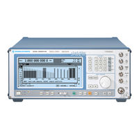
Rohde & Schwarz SMIQ03B Operating Manual (408 pages)
VECTOR SIGNAL GENERATOR
Brand:
Rohde & Schwarz
| Category:
Portable Generator
| Size: 1.5 MB
Table of Contents
Table of Contents
15
Remote Control
30
Brief Instructions
30
IEC-Bus
30
Interface
31
Switchover to Remote Control
31
Remote Control Via IEC Bus
32
Setting the Device Address
32
Indications During Remote Control
32
Return to Manual Operation
32
Remote Control Via RS-232-Interface
33
Setting the Transmission Parameters
33
Indications During Remote Control
33
Return to Manual Operating
33
Messages
33
Interface Message
33
Device Messages (Commands and Device Responses)
34
Structure and Syntax of the Device Messages
34
SCPI Introduction
34
Structure of a Command
35
Structure of a Command Line
37
Responses to Queries
37
Parameter
38
Overview of Syntax Elements
40
Description of Commands
41
Notation
41
Common Commands
43
Abort System
46
ARB System
47
ARB Waveform Format
52
Creating a Waveform „Manually
54
Converting a Waveform with the Application Software AMIQ-K2
58
AMIQ Compatible Commands for Transmission and Administration of Waveforms
58
BERT System
59
BLER System
63
Calibration System
66
Diagnostic System
69
DISPLAY System
72
Format System
73
Memory System
74
Output System
75
Output2 System
77
Source System
78
Source:am Subsystem
79
Source:correction Subsystem
80
Source:dect Subsystem
82
Source:dist Subsystem
90
Source:DM Subsystem
94
Vector Modulation
94
Digital Modulation
96
Source:fm Subsystem
107
Source:frequency Subsystem
109
Source:fsim-Subsystem
111
Source:gps Subsystem
122
Source:gsm Subsystem (Digital Standard GSM/EDGE)
125
Source:is95 Subsystem (Digital Standard IS-95 CDMA)
131
Source:list Subsystem
139
Source:marker Subsystem
141
Source:modulation Subsystem
143
Source:nadc Subsystem
144
Source:noise Subsystem
152
Source:pdc Subsystem
153
Source:phase Subsystem
162
Source:phs Subsystem
163
Source:pm Subsystem
171
Source:power Subsystem
173
Source:pulm Subsystem
176
Source:roscillator Subsystem
177
Source:sweep Subsystem
178
Source:wcdma Subsystem (NTT Docomo/Arib 0.0)
181
Source:w3Gpp-Subsystem
188
Source:w3Gpp:enhanced/Ocns/Additional Subsystems
209
Source2 System
223
Source2:Frequency Subsystem
223
Source2:Marker Subsystem
225
Source2:Sweep Subsystem
226
Status System
228
System System
230
TEST System
236
Trigger System
239
UNIT System
243
Instrument Model and Command Processing
244
Input Unit
244
Command Recognition
245
Data Set and Instrument Hardware
245
Output Unit
246
Status Reporting System
249
Overview of the Status Registers
249
Description of the Status Registers
250
Status Byte (STB) and Service Request Enable Register (SRE)
250
IST Flag and Parallel Poll Enable Register (PPE)
251
Event Status Register (ESR) and Event Status Enable Register (ESE)3.222
251
Status:operation Register
252
Status:questionable Register
253
Checking the Rated Characteristics
262
Test Equipment and Test Assemblies
262
Measuring Equipment and Accessories
262
Test Assemblies
263
Standard Test Assembly for Analog Modulations
263
Test Assembly for Analog Modulations with Audio Analyzer
264
Test Assembly for Broadband FM
264
Test Assembly for Pulse Modulation
265
Test Assembly for Vector Modulation
265
Test Assembly for SSB Phase Noise
266
Test Assembly for Output Impedance (VSWR)
266
Test Assembly with Spectrum Analyzer for Fading Simulation
267
Test Assembly with Sampling Oscilloscope for Fading Simulation
267
Test Assembly for Amplitude Settling
267
Preparation, Recommended Test Frequencies and Levels
268
Test Procedures
269
Display and Keyboard
269
Frequency
269
Frequency Setting
269
Settling Time
270
Setting Time LIST MODE
272
Reference Frequency
273
Output of Internal Reference
273
Input for External Reference
273
Level
273
Level Uncertainty
273
Output Impedance
275
Settling Time
276
Non-Interrupting Level Setting (ATTENUATOR MODE FIXED)
278
Overvoltage Protection (if Provided)
279
Spectral Purity
279
Harmonics
279
Subharmonics
280
Nonharmonics
280
Broadband Noise
283
SSB Phase Noise
284
Residual FM
285
Residual am
285
Sweep
285
Internal Modulation Generator
286
Vector Modulation
287
Input Impedance (VSWR)
287
Maximum Level
287
Error Vector
288
Modulation Frequency Response
288
Residual Carrier and Leakage
289
I/Q Imbalance
290
Level Control POW RAMP
291
Amplitude Modulation
292
Modulation Depth Setting
292
Rohde & Schwarz SMIQ03B Operating Manual (407 pages)
VECTOR SIGNAL GENERATOR
Brand:
Rohde & Schwarz
| Category:
Portable Generator
| Size: 1.37 MB
Table of Contents
Table of Contents
14
Remote Control
29
Brief Instructions
29
IEC-Bus
29
Interface
30
Switchover to Remote Control
30
Remote Control Via IEC Bus
31
Setting the Device Address
31
Indications During Remote Control
31
Return to Manual Operation
31
Remote Control Via RS-232-Interface
32
Setting the Transmission Parameters
32
Indications During Remote Control
32
Return to Manual Operating
32
Messages
32
Interface Message
32
Device Messages (Commands and Device Responses)
33
Structure and Syntax of the Device Messages
33
SCPI Introduction
33
Structure of a Command
34
Structure of a Command Line
36
Responses to Queries
36
Parameter
37
Overview of Syntax Elements
39
Description of Commands
40
Notation
40
Common Commands
42
Abort System
45
ARB System
46
ARB Waveform Format
51
Creating a Waveform „Manually
53
Converting a Waveform with the Application Software AMIQ-K2
57
AMIQ Compatible Commands for Transmission and Administration of Waveforms
57
BERT System
58
BLER System
62
Calibration System
65
Diagnostic System
68
DISPLAY System
71
Format System
72
Memory System
73
Output System
74
Output2 System
76
Source System
77
Source:am Subsystem
78
Source:correction Subsystem
79
Source:dect Subsystem
81
Source:dist Subsystem
89
Source:DM Subsystem
93
Vector Modulation
93
Digital Modulation
95
Source:fm Subsystem
106
Source:frequency Subsystem
108
Source:fsim-Subsystem
110
Source:gps Subsystem
121
Source:gsm Subsystem (Digital Standard GSM/EDGE)
124
Source:is95 Subsystem (Digital Standard IS-95 CDMA)
130
Source:list Subsystem
138
Source:marker Subsystem
140
Source:modulation Subsystem
142
Source:nadc Subsystem
143
Source:noise Subsystem
151
Source:pdc Subsystem
152
Source:phase Subsystem
161
Source:phs Subsystem
162
Source:pm Subsystem
170
Source:power Subsystem
172
Source:pulm Subsystem
175
Source:roscillator Subsystem
176
Source:sweep Subsystem
177
Source:wcdma Subsystem (NTT Docomo/Arib 0.0)
180
Source:w3Gpp-Subsystem
187
Source:w3Gpp:enhanced/Ocns/Additional Subsystems
208
Source2 System
222
Source2:Frequency Subsystem
222
Source2:Marker Subsystem
224
Source2:Sweep Subsystem
225
Status System
227
System System
229
TEST System
235
Trigger System
238
UNIT System
242
Instrument Model and Command Processing
243
Input Unit
243
Command Recognition
244
Data Set and Instrument Hardware
244
Output Unit
245
Status Reporting System
248
Overview of the Status Registers
248
Description of the Status Registers
249
Status Byte (STB) and Service Request Enable Register (SRE)
249
IST Flag and Parallel Poll Enable Register (PPE)
250
Event Status Register (ESR) and Event Status Enable Register (ESE)3.222
250
Status:operation Register
251
Status:questionable Register
252
Checking the Rated Characteristics
261
Test Equipment and Test Assemblies
261
Measuring Equipment and Accessories
261
Test Assemblies
262
Standard Test Assembly for Analog Modulations
262
Test Assembly for Analog Modulations with Audio Analyzer
263
Test Assembly for Broadband FM
263
Test Assembly for Pulse Modulation
264
Test Assembly for Vector Modulation
264
Test Assembly for SSB Phase Noise
265
Test Assembly for Output Impedance (VSWR)
265
Test Assembly with Spectrum Analyzer for Fading Simulation
266
Test Assembly with Sampling Oscilloscope for Fading Simulation
266
Test Assembly for Amplitude Settling
266
Preparation, Recommended Test Frequencies and Levels
267
Test Procedures
268
Display and Keyboard
268
Frequency
268
Frequency Setting
268
Settling Time
269
Setting Time LIST MODE
271
Reference Frequency
272
Output of Internal Reference
272
Input for External Reference
272
Level
272
Level Uncertainty
272
Output Impedance
274
Settling Time
275
Non-Interrupting Level Setting (ATTENUATOR MODE FIXED)
277
Overvoltage Protection (if Provided)
278
Spectral Purity
278
Harmonics
278
Subharmonics
279
Nonharmonics
279
Broadband Noise
282
SSB Phase Noise
283
Residual FM
284
Residual am
284
Sweep
284
Internal Modulation Generator
285
Vector Modulation
286
Input Impedance (VSWR)
286
Maximum Level
286
Error Vector
287
Modulation Frequency Response
287
Residual Carrier and Leakage
288
I/Q Imbalance
289
Level Control POW RAMP
290
Amplitude Modulation
291
Modulation Depth Setting
291
Advertisement
Advertisement
Related Products
Rohde & Schwarz SMIQ02B
Rohde & Schwarz SMIQ04B
Rohde & Schwarz SMIQ06B
Rohde & Schwarz SMIQ03HD
Rohde & Schwarz SMIQ06ATE
Rohde & Schwarz SMAB-K25
Rohde & Schwarz SMAB-K722
Rohde & Schwarz SMV03
Rohde & Schwarz SMC-K4
Rohde & Schwarz SMAB-K725
Rohde & Schwarz Categories
Measuring Instruments
Test Equipment
Portable Generator
Power Supply
Accessories
More Rohde & Schwarz Manuals
Login
Sign In
OR
Sign in with Facebook
Sign in with Google
Upload manual
Upload from disk
Upload from URL