Sign In
Upload
Manuals
Brands
Rohde & Schwarz Manuals
Measuring Instruments
R&S FSH6
Rohde & Schwarz R&S FSH6 Manuals
Manuals and User Guides for Rohde & Schwarz R&S FSH6. We have
2
Rohde & Schwarz R&S FSH6 manuals available for free PDF download: Operating Manual, Quick Start Manual
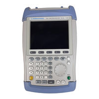
Rohde & Schwarz R&S FSH6 Operating Manual (245 pages)
Handheld Spectrum Analyzer
Brand:
Rohde & Schwarz
| Category:
Measuring Instruments
| Size: 5.66 MB
Table of Contents
Table of Contents
3
Putting into Operation
35
Front View
35
Putting into Operation
36
Unpacking the Instrument
36
Setting up the Instrument
37
Switching on the Spectrum Analyzer
38
Spectrum Analyzer Connectors
39
Screen Settings
41
Country-Specific Settings
43
Setting the Date and Time
44
Setting the Date
44
Setting the Time
44
Charging the Battery
45
Selecting the Instrument Default Setup
46
External Reference / External Trigger Switchover
47
Controlling the RF Attenuator
48
Using a Preamplifier
48
PIN Entry
50
Connecting Printers
52
Setting the Baud Rate for Remote Control
54
Enabling Options
54
Checking the Installed Options
55
Getting Started
56
Measurements on CW Signals
56
Level Measurement
56
Setting the Reference Level
57
Frequency Measurements
58
Harmonic Measurements of a Sinewave Signal
59
Power Measurements Using the Power Sensor
60
Power and Return Loss Measurements with the R&S FSH-Z14 or the R&S FSH-Z44
62
Two-Port Transmission Measurements
64
Measurement of Return Loss
66
Performing Distance-To-Fault Measurements
69
Operation in Receiver Mode
75
Measuring the Carrier-To-Noise Ratio
80
Reference Power/Reference Level
81
Measuring the Noise Power
82
Saving and Recalling Settings and Test Results
83
Saving Measurement Results
83
Saving Calibration Data
84
Recalling Measurement Results
85
Operation
87
Screen Layout
87
Screen Layout for Spectrum-Mode Measurements Without Markers
87
Screen Layout When the Marker Mode Is Selected
88
Entering Measurement Parameters
89
Entering Values and Texts
89
Entering Units
90
Menu Overview
91
Frequency Entry
91
Frequency Span
91
Level Setting
91
Bandwidth Setting
91
Sweep
92
Trace Setting
92
Measurement Functions
93
Markers
96
Save and Print Menu
97
Instrument Setup
97
Status Display
97
Menus in the Receiver Mode (Option R&S FSH-K3)
98
Instrument Functions
101
Instrument Default Setup
101
Status Display
101
Setting the Frequency
102
Entering the Center Frequency
102
Setting a Frequency Offset
102
Entering the Center-Frequency Step Size
103
Entering the Start and Stop Frequency
104
Working with Channel Tables
104
Setting the Span
106
Setting the Amplitude Parameters
107
Setting the Reference Level
108
Entering the Display Range
108
Entering the Display Unit
109
Entering the Reference Offset
109
Entering the Input Impedance
110
Setting the Bandwidths
111
Resolution Bandwidth
111
Video Bandwidth
113
Setting the Sweep
115
Sweep Time
115
Sweep Mode
116
Trigger
116
Trace Settings
119
Trace Mode
119
Detector
120
Trace Memory
122
Using the Markers
124
Automatic Marker Positioning
125
Using more than One Marker at a Time (Multimarker Mode)
127
Marker Functions
130
Measuring the Noise Power Density
130
Measuring the Frequency
131
AF Demodulation
132
Using the Display Line
133
Setting and Using the Measurement Functions
134
Measuring the Channel Power of Continuously Modulated Signals
134
Selecting the Standard
135
Setting the Reference Level
137
Setting the Channel Bandwidth
137
Changing the Span
138
Power Display
139
Power Measurements on TDMA Signals
141
Selecting a Standard
141
Setting the Measurement Time
143
Optimizing the Reference Level
143
Power Readout
144
Setting the Trigger
144
Measuring the Occupied Bandwidth
145
Selecting a Standard
146
Setting the Reference Level
147
Setting the Channel Bandwidth
148
Displaying the Occupied Bandwidth
148
Changing the Span
149
Measuring the Carrier-To-Noise Ratio
150
Determining the Reference
151
DIGITAL Tx Mode
151
ANALOG TV Mode
152
CW Tx Mode
152
Manual Reference Mode
153
Setting the Reference Channel
153
Setting the Reference Channel Bandwidth
154
Setting the Analyzer Reference Level for the Reference Channel Measurement
155
Inserting the C/N Reference
155
Units of the C/N Reference
156
Measuring the Noise Channel Power and Calculating the Carrier Power/Noise Power
156
Setting the Noise Channel
157
Setting the Noise Channel Bandwidth
158
Setting the R&S FSH Reference Level During Noise Channel Measurement
158
Selecting the C/N Result Display
159
C/N Measurement Result Display
159
Changing the Span
160
Using the R&S FSH in Receiver Mode
161
Setting the Frequency
162
Setting the Reference Level
164
Setting the Bandwidth
165
Setting the Detector
166
Setting the Measurement Time
166
Measurement on Multiple Frequencies or Channels (Scan)
167
Measurements Using the Power Sensor
169
Connecting the Power Sensor
169
Zeroing the Power Sensor
171
Selecting the Unit for the Power Readout
172
Setting the Averaging Time
173
Taking Additional Loss or Gain into Account
173
Measuring Forward and Reflected Power
175
Zeroing the Power Sensor
177
Setting the Power Measurement Weighting
178
Selecting the Unit for the Power Readout
179
Taking Additional Attenuation into Account
180
Two-Port Measurements with the Tracking Generator
182
Measuring the Transmission of Two-Ports
184
Vector Transmission Measurement
187
Transmission Measurement Using the Connected VSWR Bridge R&S FSH-Z3
189
Spectrum Measurements with the VSWR Bridge R&S FSH-Z3 or R&S FSH-Z2 Connected
190
Supplying DC Voltage to Active Duts
191
Reflection Measurements
191
Scalar Measurement of Reflection
192
Vector Measurement of Reflection
194
Display of Reflection in Vector Measurement
196
Spectrum Measurements with the VSWR Bridge R&S FSH-Z3 or R&S FSH-Z2 Connected
200
Settings for Detection of the R&S FSH-Z2 and R&S FSH-Z3
201
One-Port Measurement of Cable Loss
202
Cable Measurements
203
Cable Selection
204
Selecting the Frequency Range
207
Calibrating the Test Setup
208
Locating Cable Faults by Means of the Marker Function
211
Measuring Spectrum and Reflection
214
Further Information
215
Setting the Span
215
Selecting the Center Frequency
216
Measurement
217
Length Measurement Accuracy
217
Using Limit Lines
218
Measurements with Limit Lines
220
Definition Range of Limit Lines
221
Data Sets Containing Limit Lines
221
Measuring with Transducer Factors
222
Unit for Measurements with Transducers
224
Reference Level Settings for Measurements with Transducers
224
Frequency Range of Transducer
225
Data Sets Containing Transducer Factors
225
Field-Strength Measurement with Isotropic Antenna
226
Connecting the Antenna to the R&S FSH
226
Saving and Loading Instrument Settings and Measurement Results
235
Saving Results
236
Entering a Data Set Name
237
Loading Measurement Results
237
Deleting Saved Data Sets
238
Deleting All Data Sets
239
Printing out Measurement Results
240
Measurements
241
How a Spectrum Analyzer Operates
241
Advertisement
Rohde & Schwarz R&S FSH6 Quick Start Manual (60 pages)
Handheld Spectrum Analyzer
Brand:
Rohde & Schwarz
| Category:
Measuring Instruments
| Size: 1.63 MB
Advertisement
Related Products
Rohde & Schwarz R&S FSH626
Rohde & Schwarz R&S FSH Series
Rohde & Schwarz R&S FSH3
Rohde & Schwarz R&S FSH
Rohde & Schwarz R&S FSH-Z1
Rohde & Schwarz R&S FSH-Z2
Rohde & Schwarz R&S FSH323
Rohde & Schwarz R&S FSH313
Rohde & Schwarz R&S FSH18
Rohde & Schwarz R&S FSH13
Rohde & Schwarz Categories
Measuring Instruments
Test Equipment
Portable Generator
Power Supply
Accessories
More Rohde & Schwarz Manuals
Login
Sign In
OR
Sign in with Facebook
Sign in with Google
Upload manual
Upload from disk
Upload from URL