Sign In
Upload
Manuals
Brands
Rockwell Automation Manuals
I/O Systems
Allen-Bradley ArmorBlock 5032-8IOLM12DR
Rockwell Automation Allen-Bradley ArmorBlock 5032-8IOLM12DR Manuals
Manuals and User Guides for Rockwell Automation Allen-Bradley ArmorBlock 5032-8IOLM12DR. We have
1
Rockwell Automation Allen-Bradley ArmorBlock 5032-8IOLM12DR manual available for free PDF download: User Manual
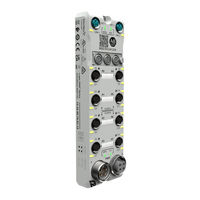
Rockwell Automation Allen-Bradley ArmorBlock 5032-8IOLM12DR User Manual (124 pages)
8-channel IO-Link Master Module
Brand:
Rockwell Automation
| Category:
I/O Systems
| Size: 11.13 MB
Table of Contents
Table of Contents
3
Preface
7
About this Publication
7
Download Firmware, AOP, EDS, and Other Files
7
Additional Resources
7
Introduction
9
Highly Integrated IO-Link
9
Controller and Software Compatibility
10
Module Overview
11
Secure Access to the System
12
Ownership
12
Power the Module
12
Module and Device Configuration
13
Module and Device Operation
13
Requested Packet Interval
13
Cyclic Mode
13
Change of State Mode
14
Connections
14
Protected Operations
15
Module Features
17
Software Configurable
17
Configurable Channel Modes
17
Fault and Status Reporting
17
Module Inhibiting
18
Electronic Keying
18
Update Module Firmware
19
Input Events
19
Independent Point Trigger
19
Pattern Match Trigger
20
Input Event Latching
20
Additional Event Considerations
20
Use CIP Sync Time
20
Protected Mode for IO-Link Master Module
21
Enter and Exit Implicit Protected Mode
21
Enter and Exit Explicit Protected Mode
21
Restrictions Imposed by Implicit Protected Mode
22
Restrictions Imposed by Explicit Protected Mode
22
Perform Tasks When Restricted
22
I/O Channel Features
23
Software Configurable Input Filters
23
Input Timestamping
23
Pulse Latching
24
Chatter Detection
24
Configure Channel Output State When Module Is in Program Mode or Inhibited
24
Configure Channel Output State in Fault Mode
25
Output Behavior Immediately after a Connection Fault
25
Fault Mode State Duration after Connection Fault
25
Final Fault Mode State Value
25
Short Circuit Protection
25
Group Short Circuit
26
No Load Diagnostics
26
Fault and Status Reporting
27
Common Features of IO-Link Device Integration
29
IO-Link Device Identity
29
IO-Link Bus
29
IODD-Based AOP for IO-Link Devices
29
Fallback Mode
30
IO-Link Device Connection
30
Connection Types
30
IO-Link Device Inhibiting
31
IO-Link Device Electronic Keying
31
Automatic Device Configuration
31
Configuration Tags
32
Data Storage
32
IO-Link Device Parameters Classification
33
Device Configuration
33
Device Correlation Check
34
Get/Set IO-Link Device Parameters
34
Or Inhibited
34
Configure Process Data Output State in Fault Mode
34
IO-Link Device Information and Diagnostics
35
Fault and Status Reporting
35
IO-Link Device Configuration Change Notification
35
Execute IO-Link Commands through Explicit Messaging
36
Protected Mode for IO-Link Devices
36
Enter and Exit Protected Mode
36
Restrictions Imposed by Protected Mode
37
IO-Link Events
37
Configure the IO-Link Master Module
39
Configure the Module IP Address
39
Set the Network Address Switches
39
Use the BOOTP/DHCP Tool
40
Add the Module to a Studio 5000 Logix Designer Application Project
40
Discover Modules
41
New Module
42
Edit the Module Properties
44
General View
45
Connection View
48
Module Info View
49
Channels View
49
Input Events View
53
Internet Protocol View
56
Port Configuration View
57
Network View
57
Time Sync View
58
Servers View
59
Switch Channel Mode from IO-Link or Fallback to Digital Output
60
Reset Module to Factory Default
60
Configure the IO-Link Device
61
Before You Begin
61
Register IO-Link Device IODD
61
Add IO-Link Devices to Your Project
63
Discover Modules
63
New Module
65
Add a Preconfigured Device
66
Edit the IO-Link Device Properties
67
General View
68
Connection View
69
Device Info View
70
Configuration View
71
Parameters View
72
Replace IO-Link Devices
73
Prerequisite Steps
74
Replace a Device with ADC Disabled and DS Not Supported
74
Replace with a Used Device When ADC Disabled and DS Supported
74
Replace a Device on a Fallback Channel
75
Replace with a Used Master Module When any Device Supports DS and ADC Disabled
75
Replace a Master Module and Devices with Device ADC Disabled
75
Adjust Device Configuration after Replacement
76
After Adjusting the Device Configuration
76
Clone/Duplicate a Machine
76
Reset IO-Link Device to Factory Default
77
Troubleshoot Your IO-Link Master Module
79
Module Status Indicator
79
Network Status Indicator
79
Link Status Indicator
80
Power Status Indicator
80
Channel Status Indicator
80
Troubleshoot Wiring Issues
81
Use the Studio 5000 Logix Designer Application for Troubleshooting
82
Warning Signal in the I/O Configuration Tree
82
Status and Fault Information in Module Properties
82
Diagnostics in Studio 5000 Logix Designer Application
84
Studio 5000 Logix Designer Application Tag Editor
86
Module Diagnostic Webpages
87
Troubleshoot Your IO-Link Device
89
Warning Signal in the I/O Configuration Tree
89
Status and Fault Information in Module Properties
90
General Troubleshooting Tips for Configuration and Connection Issues
92
Studio 5000 Logix Designer Application Tag Editor
94
IO-Link Event Log
95
Use CIP Messages to Retrieve the IO-Link Event Log
96
IO-Link Master Module and IO-Link Device Tag Definitions
97
Tag Name Conventions
97
Access the Tags
97
IO-Link Master Module Tags
98
Configuration Tags for IO-Link Master Module
98
Input Tags for IO-Link Master Module
100
Output Tags for IO-Link Master Module
102
Event Input Tags for IO-Link Master Module
103
Event Output Tags for IO-Link Master Module
104
Status Tags for IO-Link Master Module
105
IO-Link Device Tags
106
Configuration Tags for IO-Link Device
107
Input Tags for IO-Link Device
107
Output Tags for IO-Link Device
108
Module Diagnostic Assembly
109
Create User-Defined Diagnostic Assembly Types
109
Diagnostic Assemblies
109
Diagnostic Channels
113
Create Message Type User Tags
114
IO-Link Connectivity
117
Example Diagram
117
Advertisement
Advertisement
Related Products
Rockwell Automation Allen-Bradley ArmorBlock 5032-8IOLM12M12LDR
Rockwell Automation Allen-Bradley ArmorBlock 5032-8IOLM12P5DR
Rockwell Automation Allen-Bradley 5069-L330ERMK
Rockwell Automation Allen-Bradley 5069-L340ERM
Rockwell Automation Allen-Bradley 5069-L330ERM
Rockwell Automation Allen-Bradley 5069-L46ERMW
Rockwell Automation Allen-Bradley 5069-L450ERMW
Rockwell Automation Allen-Bradley 5069-L320ERS2K
Rockwell Automation Allen-Bradley 5069-L330ERMS2
Rockwell Automation Allen-Bradley 5069-L380ERMS2
Rockwell Automation Categories
Controller
Control Unit
Power Supply
DC Drives
Industrial Equipment
More Rockwell Automation Manuals
Login
Sign In
OR
Sign in with Facebook
Sign in with Google
Upload manual
Upload from disk
Upload from URL