Sign In
Upload
Manuals
Brands
Rockwell Automation Manuals
Relays
440R-S12R2
Rockwell Automation 440R-S12R2 Manuals
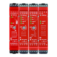
Manuals and User Guides for Rockwell Automation 440R-S12R2. We have
2
Rockwell Automation 440R-S12R2 manuals available for free PDF download: User Manual
Rockwell Automation 440R-S12R2 User Manual (90 pages)
Safety Relays
Brand:
Rockwell Automation
| Category:
Relays
| Size: 15.31 MB
Table of Contents
Table of Contents
3
Definitions
7
Preface
7
Summary of Changes
7
Who Should Use this Manual
7
Additional Resources
8
Chapter 1 Hardware Features
9
Multi-Position Switches
9
Overview
9
Removable Terminal Blocks
9
Status Indicators
9
CI Safety Relay (Cat. No. 440R-S13R2)
10
DI Safety Relay (Cat. No. 440R-D22R2)
10
DIS Safety Relay (Cat. No. 440R-D22S2)
10
EM Safety Relay (Cat. No. 440R-EM4R2)
10
EMD Safety Relay (Cat. No. 440R-EM4R2D)
10
Optical Communication Bus
10
Safety Relay (Cat. No. 440R-S12R2)
11
Chapter 2 Mounting Dimensions
13
DIN Rail Mounting and Removal
13
Removal
13
Spacing
14
Installation
13
Enclosure Considerations
14
Removable Terminals
14
Help Prevent Excessive Heat
15
Chapter 3 Wiring Requirements and Recommendation
17
Wire Size
17
Terminal Torque
17
Terminal Assignments
17
Power, Ground, and Wire
17
Connect a Power Supply
19
Ground the Relay
19
Safety Inputs
19
Devices with Mechanical Contacts
19
Devices with OSSD Output
20
Safety Mats
22
Safedge Safety Edges
23
Safety Outputs
24
Electromechanical Outputs
24
OSSD Outputs
24
Surge Suppressors
25
Single Wire Safety Input and Output
26
Auxiliary Output
27
Reset and Monitor Input
27
Automatic/Manual Reset
28
Monitored Reset
28
Monitor with Expansion Relays
29
Retriggerable Input
29
Jog Input
30
Chapter 4 Switch Adjustment
31
DI and DIS Safety Relays
32
EMD Safety Relay
32
Configuration Process
33
Five Steps to Configure Your GSR Safety Relay
33
Chapter 5 Indicators During Power-Up
35
Indicators During Normal Operation
35
Indicators During Diagnostics
36
Chapter 6
37
CI Safety Relay
37
DI, DIS, and si Safety Relays
37
Pulse Testing for Inputs
37
Pulse Testing for OSSD Outputs
38
Chapter 7
39
Case 1
39
Case 2
39
Case 3
40
Off Delay, Non-Retriggerable
39
Off Delay, Retriggerable
40
Case 1
40
Case 2
40
On Delay
40
Case 1
41
Case 2
41
Jog
41
Case 1
42
Case 2
42
Case 3
42
Chapter 8
43
CI Safety Relay (Cat. No. 440R-S13R2)
43
DI Safety Relay (Cat. No. 440R-D22R2)
43
DIS Safety Relay (Cat. No. 440R-D22S2)
43
EM Safety Relay (Cat. No. 440R-EM4R2)
44
EMD Safety Relay (Cat. No. 440R-EM4R2D)
44
Safety Relay (Cat. No. 440R-S12R2)
44
Application and Wiring Examples
45
Chapter 9
45
CI Safety Relay (Cat. No. 440R-S13R2)
45
DI Safety Relay (Cat. No. 440R-D22R2)
46
DIS Safety Relay (Cat. No. 440R-D22S2)
47
EM Safety Relay (Cat. No. 440R-EM4R2)
48
EMD Safety Relay (Cat. No. 440R-EM4R2D)
48
Safety Relay (Cat. No. 440R-S12R2)
50
Chapter 10 Webpage
51
Ethernet Communication
51
Studio 5000 Logix Designer Add-On Profile (AOP)
52
Chapter 11 Tools Needed
53
Required Tools
53
Optional Tools
53
Follow These Steps
53
Troubleshooting
53
View the Pwr/Fault Status Indicator (Step 1)
54
Check the Power Supply (Step 2)
56
Check Voltage
56
Verify Grounding at the Power Supply
57
Check Safety Device Inputs (Step 3)
58
Check Voltage-Free Contacts
58
Examine Pulse Test Waveforms
60
Effect of OSSD Test Pulses
61
Detect off Pulses
61
Capacitance Effect
61
Long Wire - Resistance Effect
62
Channel Simultaneity (Discrepancy)
63
Multiple-Channel Cycling
63
Recovery Time
64
Check the Single Wire Safety Circuit (Step 4)
64
SWS Connections L11 and L12
65
Check the Reset/Monitoring Circuit (Step 5)
66
Two-Handed Reset Operation
67
Applications with OSSD Outputs and Test Pulses
67
Check the Safety Outputs (Step 6)
67
Electromechanical Output Issues
67
OSSD Output Issues
69
Auxiliary Output Issues
72
EMD Expansion Safety Relay B1/B2 Inputs (Step 7)
74
Terminal Block Removal and Replacement
75
Terminal Block Removal
75
Terminal Block Replacement
75
Series, Version, and Manufacturing Date Code
76
Current Product Label
76
Old Product Label
76
Appendix A General Specifications
77
Environmental Specifications
77
Safety Inputs IN, IN1, and IN2 Specifications
77
B1 Input Specifications
78
Reset Input Specifications
78
Auxiliary Output Specification
79
Safety Outputs Specifications
79
Single Wire Safety (SWS) Specifications
80
Appendix B Agency Certifications
83
Compliance with European Union Directives
83
EMC Directive
83
Machine Safety Directive
83
SIL Rating
84
Performance Level/Category
84
Index
85
Advertisement
Rockwell Automation 440R-S12R2 User Manual (88 pages)
Guardmaster Safety Relays
Brand:
Rockwell Automation
| Category:
Relays
| Size: 15.38 MB
Table of Contents
Table of Contents
3
Who Should Use this Manual
7
Summary of Changes
7
Download Firmware, AOP, EDS, and Other Files
7
Definitions
8
Additional Resources
8
Overview
9
Hardware Features
9
Removable Terminal Blocks
9
Status Indicators
9
Multi-Position Switches
9
Optical Communication Bus
10
CI Safety Relay (Cat. No. 440R-S13R2)
10
DI Safety Relay (Cat. No. 440R-D22R2)
10
DIS Safety Relay (Cat. No. 440R-D22S2)
10
EM Safety Relay (Cat. No. 440R-EM4R2)
10
EMD Safety Relay (Cat. No. 440R-EM4R2D)
10
Safety Relay (Cat. No. 440R-S12R2)
11
Installation
13
Mounting Dimensions
13
DIN Rail Mounting and Removal
13
Removal
13
Spacing
14
Removable Terminals
14
Enclosure Considerations
14
Help Prevent Excessive Heat
15
Power, Ground, and Wire
17
Wiring Requirements and Recommendation
17
Wire Size
17
Terminal Torque
17
Terminal Assignments
17
Ground the Safety Relay
19
Connect a Power Supply
19
Safety Inputs
19
Devices with Mechanical Contacts
19
Devices with OSSD Output
20
Safety Mats
21
Safedge Safety Edges
23
Safety Outputs
24
Electromechanical Outputs
24
OSSD Outputs
24
Surge Suppressors
25
Single Wire Safety Input and Output
26
Auxiliary Output
26
Reset and Monitor Input
27
Automatic/Manual Reset
27
Monitored Reset
28
Monitor with Expansion Relays
29
Retriggerable Input
29
Jog Input
29
Configuration
31
Introduction
31
Switch Adjustment
31
DI and DIS Safety Relays
32
EMD Safety Relay
32
Configuration Process
33
Five Steps to Configure Your GSR Safety Relay
33
Status Indicators
35
Status Indicators During Power-Up
35
Status Indicators During Normal Operation
35
Status Indicators During Diagnostics
36
Pulse Testing Functions
37
Pulse Testing for Inputs
37
CI Safety Relay
37
DI, DIS, and si Safety Relays
37
Pulse Testing for OSSD Outputs
38
EMD Safety Relay Timing Functions
39
Off Delay, Non-Retriggerable
39
Case 1
39
Case 2
39
Case 3
40
Off Delay, Retriggerable
40
Case 1
40
Case 2
40
On Delay
40
Case 1
41
Case 2
41
Jog
41
Case 3
42
Internal Circuit Block Diagrams
43
CI Safety Relay (Cat. No. 440R-S13R2)
43
DI Safety Relay (Cat. No. 440R-D22R2)
43
DIS Safety Relay (Cat. No. 440R-D22S2)
43
EM Safety Relay (Cat. No. 440R-EM4R2)
43
EMD Safety Relay (Cat. No. 440R-EM4R2D)
44
Safety Relay (Cat. No. 440R-S12R2)
44
Application and Wiring Examples
45
CI Safety Relay (Cat. No. 440R-S13R2)
45
DI Safety Relay (Cat. No. 440R-D22R2)
46
DIS Safety Relay (Cat. No. 440R-D22S2)
47
EM Safety Relay (Cat. No. 440R-EM4R2)
48
EMD Safety Relay (Cat. No. 440R-EM4R2D)
48
Safety Relay (Cat. No. 440R-S12R2)
50
Ethernet Communication
51
Webpage
51
Studio 5000 Logix Designer Add-On Profile (AOP)
52
Troubleshooting
53
Tools Needed
53
Required Tools
53
Optional Tools
53
Follow These Steps
53
View the Pwr/Fault Status Indicator (Step 1)
54
Check the Power Supply (Step 2)
56
Check Voltage
56
Verify Grounding at the Power Supply
57
Check Safety Device Inputs (Step 3)
58
Check Voltage-Free Contacts
58
Examine Pulse Test Waveforms
60
Effect of OSSD Test Pulses
61
Detect off Pulses
61
Capacitance Effect
61
Long Wire - Resistance Effect
62
Channel Simultaneity (Discrepancy)
63
Multiple-Channel Cycling
63
Recovery Time
64
Check the Single Wire Safety Circuit (Step 4)
64
SWS Connections L11 and L12
64
Check the Reset/Monitoring Circuit (Step 5)
66
Two-Handed Reset Operation
67
Applications with OSSD Outputs and Test Pulses
67
Check the Safety Outputs (Step 6)
67
Electromechanical Output Issues
67
OSSD Output Issues
69
Auxiliary Output Issues
71
EMD Expansion Safety Relay B1/B2 Inputs (Step 7)
74
Terminal Block Removal and Replacement
75
Terminal Block Removal
75
Terminal Block Replacement
75
Series, Version, and Manufacturing Date Code
76
Current Product Label
76
Old Product Label
76
Specifications
77
General
77
Environmental
77
Safety Inputs IN, IN1, and IN2
78
Reset Input
78
B1 Input
79
Safety Outputs
79
Auxiliary Output
80
Single Wire Safety (SWS)
80
Regulatory Approvals
81
Agency Certifications
81
Declaration of Conformity
81
CE Conformity
81
UKCA Conformity
81
Machine Safety Directive
82
SIL Rating
82
Performance Level/Category
82
Advertisement
Related Products
Rockwell Automation 440R-S13R2
Rockwell Automation Allen-Bradley Guardmaster 440R-S35013
Rockwell Automation Allen-Bradley Guardmaster 440R-S35012
Rockwell Automation Allen-Bradley Guardmaster 440R-S35011
Rockwell Automation Allen-Bradley Guardmaster 440R-S35014
Rockwell Automation Allen-Bradley Guardmaster 440R-S35015
Rockwell Automation Allen-Bradley Guardmaster 440R-S35016
Rockwell Automation 440R-S845AER-NNL
Rockwell Automation Guardmaster Allen-Bradley 440R-S35001
Rockwell Automation Guardmaster Allen-Bradley 440R-S35003
Rockwell Automation Categories
Controller
Control Unit
Power Supply
DC Drives
Industrial Equipment
More Rockwell Automation Manuals
Login
Sign In
OR
Sign in with Facebook
Sign in with Google
Upload manual
Upload from disk
Upload from URL