Sign In
Upload
Manuals
Brands
Rockwell Automation Manuals
Servo Drives
2198-C4007-ERS
Rockwell Automation 2198-C4007-ERS Manuals
Manuals and User Guides for Rockwell Automation 2198-C4007-ERS. We have
3
Rockwell Automation 2198-C4007-ERS manuals available for free PDF download: User Manual, Migration Manual, Installation Instructions Manual
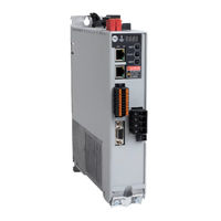
Rockwell Automation 2198-C4007-ERS User Manual (246 pages)
Single-axis EtherNet/IP Servo Drives
Brand:
Rockwell Automation
| Category:
Servo Drives
| Size: 36.03 MB
Table of Contents
Table of Contents
3
Preface
9
About this Publication
9
Summary of Changes
9
Download Firmware, AOP, EDS, and Other Files
9
Conventions Used in this Manual
9
Access Fault Codes
9
CIP Security
10
Additional Resources
10
About the Kinetix 5300
14
Servo Drive System
14
Drive Hardware and Input Power Configurations
15
Motor and Auxiliary Feedback Configurations
18
Typical Communication Configurations
19
Linear Topology
19
Ring Topology
20
Star Topology
21
Safe Torque off Configuration
22
Catalog Number Explanation
23
Agency Compliance
24
System Design Guidelines
25
System Mounting Requirements
25
AC Line Filter Selection
26
Transformer Selection
27
Circuit Breaker/Fuse Selection
27
24V Control Power Evaluation
29
Passive Shunt Considerations
30
Enclosure Selection
31
Minimum Clearance Requirements
33
Electrical Noise Reduction
34
HF Bond for Modules
34
HF Bond for Multiple Subpanels
36
Establish Noise Zones
37
Cable Categories for Kinetix 5300 Systems
38
Noise Reduction Guidelines for Drive Accessories
38
Determine Mounting Order
42
Zero-Stack Tab and Cutout
42
Shared-Bus Connection System
42
Drill-Hole Patterns
44
Mount Your Kinetix 5300 Drive
50
Connector Data and Feature Descriptions
52
Kinetix 5300 Connector Data
52
Safe Torque off Connector Pinout
52
Input Power Connector Pinouts
53
Shunt Resistor Connector Pinouts
53
Ethernet Communication Connector Pinout
53
Digital Inputs and Auxiliary Feedback Connector Pinouts
54
Motor Power, Brake, and Feedback Connector Pinouts
54
Understand Control Signal Specifications
56
Digital Inputs
56
Motor Holding-Brake Circuit
56
Control Power
58
Ethernet Communication Specifications
58
Feedback Specifications
58
Motor Feedback Supported on the MFB Connector
59
Auxiliary Feedback Specifications
61
Encoder Phasing Definitions
63
Absolute Position Feature
64
Safe Torque off Safety Features
65
Servo Drives with Hardwired Safety
65
Connect the Kinetix 5300 Drive System
67
Basic Wiring Requirements
67
Build Your Own Cables
68
Routing the Power and Signal Cables
68
Determine the Input Power Configuration
69
Three-Phase Input Power
69
Single-Phase Input Power
70
Ground the Drive System
71
Ground the System Subpanel
71
Ground Multiple Subpanels
72
Wiring Requirements
73
Wiring Guidelines
75
Wire the Power Connectors
76
Wire the 24V Control Power Input Connector
76
Wire the Input Power Connector
77
Wire the Digital Input Connectors
77
Wire the Safe Torque off Connector
77
Wire the Digital Inputs and Auxiliary Feedback Connector
78
Wire the Motor Power and Brake Connectors
79
Servo Motor/Actuator and Cable Compatibility
80
Motor Power and Brake Connections
80
Maximum Cable Lengths
82
Cable Preparation for Kinetix TLP Motor Power Cables
83
Cable Preparation for 2090-Cpxm7Df Motor Power Cables
83
Cable Preparation for Kinetix TL and TLY Motor Power Cables
86
Apply the Motor Power/Brake Shield Clamp
87
Wire the Motor Feedback Connector
89
Cable Preparation for Kinetix TLP Feedback Cables
90
Cable Preparation for 2090-Cfbm7Dx Feedback Cables
90
Cable Preparation for Kinetix TL and TLY Feedback Cables
91
Motor Feedback Cable Preparation
92
Kinetix 2090 Feedback Cable Pinouts
93
External Passive-Shunt Resistor Connections
96
Ethernet Cable Connections
97
Configure and Start up the Kinetix 5300 Drive System
99
Understand the Kinetix 5300 Front Panel
99
Menus and Display Screen
100
Startup Sequence
104
Configure the Kinetix 5300 Drive
105
Set the Network Parameters
105
Studio 5000 Logix Designer
106
Version History
106
Install the Kinetix 5300 Add-On Profile
107
Configure the Logix 5000 Controller
107
Configure the Kinetix 5300 Drive Modules
110
Configure Drive Connections
110
Continue Drive Configuration
112
Configure the Motion Group
115
Configure Vertical Load Control Axis Properties
116
Configure Feedback-Only
116
Axis Properties
116
Configure Induction-Motor Frequency-Control Axis Properties
118
General and Motor Categories
118
Basic Volts/Hertz Method
119
Sensorless Vector Method
119
Fan/Pump Volts/Hertz Method
121
Configure SPM Motor Closed-Loop Control Axis Properties
122
Configure Induction-Motor Closed-Loop Control Axis Properties
128
Configure Feedback Properties
133
Configure Module Properties
133
Configure Axis Properties
134
Apply Power to the Kinetix 5300 Drive
137
Test and Tune the Axes
138
Test the Axes
138
Tune the Axes
140
Troubleshoot the Kinetix 5300 Drive System
141
Safety Precautions
141
Interpret Status Indicators
141
Fault Code Overview
142
Fault Codes
143
Kinetix 5300 Drive Status Indicators
143
General Troubleshooting
144
Logix 5000 Controller and Drive Behavior
145
Web Server Interface
150
Before You Begin
155
Remove and Replace Kinetix 5300 Servo Drives
156
Remove Power and All Connections
156
Remove the Servo Drive
157
Replace the Servo Drive
157
Start and Configure the Drive
158
Certification
159
Important Safety Considerations
159
Category 3 Requirements According to ISO 13849-1
160
Stop Category Definition
160
Performance Level (PL) and Safety Integrity Level (SIL)
160
Description of Operation
160
Fault Codes
162
Probability of Dangerous Failure Per Hour
164
Safe Torque off Connector Data
164
Wire the Safe Torque off Circuit
165
Safe Torque off Wiring Requirements
165
Safe Torque off Feature
166
Safe Torque off Feature Bypass
166
Cascade the Safe Torque-Off Signal
167
STO Recovery Time
167
Safe Torque off Specifications
168
Interconnect Diagram Notes
169
Power Wiring Examples
170
Shunt Resistor Wiring Example
172
Kinetix 5300 Servo Drive and Rotary Motor Wiring Examples
173
Kinetix 5300 Drive and Linear Actuator Wiring Examples
179
System Block Diagrams
184
Before You Begin
185
Inhibit the Module
186
Upgrade Your Firmware
187
Use Controlflash Plus Software to Upgrade Your Drive
187
Firmware
187
Use Controlflash Software to Upgrade Your Drive Firmware
191
Verify the Firmware Upgrade
195
Motor Control Feature Support
197
Frequency Control Methods
198
Basic Volts/Hertz
199
Basic Volts/Hertz for Fan/Pump Applications
200
Sensorless Vector
201
Current Limiting for Frequency Control
202
The Effects of Current Limiting
202
Enable the Current Limiting Feature
204
Set the Currentvectorlimit Attribute Value
204
Stability Control for Frequency Control
205
Enable the Stability Control Feature
206
Skip Speeds
207
Multiple Skip Speeds
208
Flux up
209
Flux up Attributes
210
Configure the Flux up Attributes
211
Current Regulator Loop Settings
212
Motor Category
212
Motor Tests and Autotune Procedure
214
Motor Analyzer Category Troubleshooting
215
Selection of Motor Thermal Models
217
Generic Motors
217
Thermally Characterized Motors
218
Speed Limited Adjustable Torque (SLAT)
219
Motion Polarity Setting
219
SLAT Min Speed/Torque
219
SLAT Max Speed/Torque
220
SLAT Attributes
221
Configure the Axis for SLAT
221
Motion Drive Start (MDS) Instruction
224
Motor Overload Retention
229
Phase Loss Detection
230
Phase-Loss Detection Configuration
231
Phase Loss Detection Current Example
232
Velocity Droop
233
Closed Loop Control
233
Frequency Control
233
Velocity Droop Attribute
233
Velocity Droop Configuration
234
Commutation Self-Sensing Startup
234
Commutation Test
236
Adaptive Tuning
236
Virtual Torque Sensor
237
Advertisement
Rockwell Automation 2198-C4007-ERS Migration Manual (54 pages)
Brand:
Rockwell Automation
| Category:
Servo Drives
| Size: 6.18 MB
Table of Contents
Table of Contents
3
Application Conversion
5
Migration Options
5
Potential Design Changes
5
Preface
5
Additional Resources
6
Replacement Considerations
7
Chapter 1 Catalog Number Explanation
8
Select a Replacement Drive
8
Drive Replacement
9
Nominal Voltage and Output Current Comparison
9
Dimension Comparison
10
AC Input Power Cable Length and Fuse Protection
11
AC Input Power Configuration
11
Input Power Cable Length and Fuse Protection
11
Circuit Breaker and Fuse Considerations
12
Power Specifications
13
I/O Availability and Specifications
17
Digital Inputs
17
Motor Brake Output
20
Control and Auxiliary Power Specifications
22
Kinetix Motor and Actuator Compatibility
23
Feedback Devices
23
Accessories
24
Required Accessories
25
Optional Drive Accessories
26
Communication
26
Chapter 2 Kinetix 350 Servo Drive Connector Locations
27
Kinetix 5300 Servo Drive Connector Locations
28
I/O Connector and Auxiliary Feedback Pinouts
28
Motor Feedback
30
Safe Torque off Connector
31
Connectors
27
Chapter 3 Dimension Drawings
33
Cables
36
Power Wiring
37
Kinetix 350 Power Wiring Diagrams
37
Kinetix 5300 Power Wiring Diagrams
40
Dimensions, Cables, and Wiring
33
Chapter 4 Drive System Overview
43
Kinetix 350 Servo Drive System Architecture
45
Kinetix 5300 Drive Hardware and Input Power Configurations
46
Typical Communication Configurations
48
System Architecture
43
Appendix A
51
Feature Comparison
51
Rockwell Automation 2198-C4007-ERS Installation Instructions Manual (13 pages)
Single-axis EtherNet/IP Servo Drives
Brand:
Rockwell Automation
| Category:
Servo Drives
| Size: 4.04 MB
Table of Contents
Before You Begin
2
Product Dimensions
3
Connector Data
4
Wiring Requirements
6
Attach the Motor Cable Shield Clamp
8
Circuit Breaker/Fuse Selection
9
Motor Overload Protection
11
Additional Resources
11
Waste Electrical and Electronic Equipment (WEEE)
12
Advertisement
Advertisement
Related Products
Rockwell Automation 2198-C4004-ERS
Rockwell Automation 2198-C4015-ERS
Rockwell Automation 2198-C4020-ERS
Rockwell Automation 2198-C4030-ERS
Rockwell Automation 2198-C4055-ERS
Rockwell Automation 2198-C4075-ERS
Rockwell Automation 2198-C1007-ERS
Rockwell Automation 2198-C2030-ERS
Rockwell Automation 2198-C2075-ERS
Rockwell Automation 2198-CAPMOD-2240
Rockwell Automation Categories
Controller
Control Unit
Power Supply
DC Drives
Industrial Equipment
More Rockwell Automation Manuals
Login
Sign In
OR
Sign in with Facebook
Sign in with Google
Upload manual
Upload from disk
Upload from URL