Sign In
Upload
Manuals
Brands
Rockwell Automation Manuals
Controller
1766-L32BXB
Rockwell Automation 1766-L32BXB Manuals
Manuals and User Guides for Rockwell Automation 1766-L32BXB. We have
3
Rockwell Automation 1766-L32BXB manuals available for free PDF download: User Manual, Installation Instructions Manual
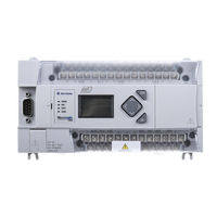
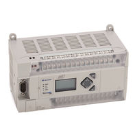
Rockwell Automation 1766-L32BXB User Manual (310 pages)
Brand:
Rockwell Automation
| Category:
Controller
| Size: 17.28 MB
Table of Contents
Table of Contents
3
Preface
11
About this Publication
11
Purpose of this Manual
11
Download Firmware, AOP, EDS, and Other Files
11
Summary of Changes
11
Additional Resources
11
Hardware Overview
13
Hardware Features
13
Component Descriptions
14
Micrologix 1400 Memory Module and Built-In Real-Time Clock
14
1762 Expansion I/O
15
Communication Cables
15
Programming
16
Firmware Revision History
16
Communication Options
17
Install Your Controller
19
Installation Considerations
19
Safety Considerations
20
Hazardous Location Considerations
20
Disconnect Main Power
20
Safety Circuits
21
Power Distribution
21
Periodic Tests of Master Control Relay Circuit
21
Power Considerations
21
Isolation Transformers
21
Power Supply Inrush
21
Loss of Power Source
22
Input States on Power down
22
Other Types of Line Conditions
22
Prevent Excessive Heat
22
Master Control Relay
23
Emergency-Stop Switches
23
Install a Memory Module
25
Use the Battery
26
Connect the Battery Wire Connector
26
Controller Mounting Dimensions
27
Controller and Expansion I/O Spacing
27
Mount the Controller
28
DIN Rail Mounting
28
Panel Mounting
29
1762 Expansion I/O Dimensions
30
Mount 1762 Expansion I/O
30
DIN Rail Mounting
30
Panel Mounting
31
Connect Expansion I/O
31
Wiring Requirements
33
Wiring Recommendation
33
Wire Without Spade Lugs
34
Wire with Spade Lugs
34
Use Surge Suppressors
34
Recommended Surge Suppressors
36
Ground the Controller
36
Wiring Diagrams
37
Terminal Block Layouts
38
Sinking and Sourcing Wiring Diagrams
40
1766-L32BWA, 1766-L32AWA, 1766-L32BXB, 1766-L32BWAA, 1766- L32AWAA, 1766-L32BXBA Wiring Diagrams
40
Controller I/O Wiring
42
Minimize Electrical Noise
42
Wire Your Analog Channels
43
Analog Channel Wiring Guidelines
43
Minimize Electrical Noise on Analog Channels
44
Ground Your Analog Cable
44
Expansion I/O Wiring
45
Digital Wiring Diagrams
45
Analog Wiring
51
Communication Connections
57
Supported Communication Protocols
57
Default Communication Configuration
58
Use the Communications Toggle Functionality
58
Change Communication Configuration
59
Connect to the RS-232 Port
60
Make a DF1 Point-To-Point Connection
61
Modem
61
Connect to a DF1 Half-Duplex Network
63
Connect to a RS-485 Network
65
DH-485 Configuration Parameters
65
Recommended Tools
67
DH-485 Communication Cable
67
Connect the Communication Cable to the DH-485 Connector
67
Ground and Terminate the DH-485 Network
68
Connect the AIC
69
Cable Selection Guide
70
Recommended User-Supplied Components
71
Install and Attach the AIC
72
Power the AIC
73
Connect to Ethernet
74
Ethernet Connections
74
LCD and Keypad
75
Operating Principles
76
Startup Screen
76
Main Menu and Default Screen
77
Operating Buttons
79
Select between Menu Items
79
Cursor Display
80
Set Values
80
I/O Status
80
View I/O Status
81
Monitor User Defined Target Files
82
Target User Defined File Number (TUF)
82
Monitor a Bit File
83
Monitor Integer Files
85
Monitor Double Integer Files
89
Monitor Floating Point Files
93
Monitor System Status Files
94
Mode Switch
94
Controller Modes
94
Change Mode Switch Position
95
User-Defined LCD Screen
96
Configure Advanced Settings
97
Change Key in Mode
98
Key in Modes
98
Communications Toggle Functionality
99
Ethernet Network Configuration
99
View Ethernet Status
99
Configure the IP Address
101
Configure the Ethernet Port
103
Configure Ethernet Protocol Setup
105
Trim Pots
107
Trim Pot Operation
107
Change Data Value of a Trim Pot
107
Trim Pot Configuration in LCD Function File
109
Error Conditions
109
View System Information
109
View Fault Code
110
Save or Load Communication EEPROM
111
Save Communication EEPROM
111
Load Communication EEPROM
112
LCD Setup
113
Configure Contrast Value
113
Configure the Back Light
114
Protocol Configuration
115
Modbus RTU Slave Node Address
115
LCD Password Setup
117
Set the LCD Password
117
Activate the LCD Password
118
Deactivate the LCD Password
119
Change LCD Password
120
Real-Time Clock Operation
123
Operation at Power-Up and Entering a Run or Test Mode
123
Write Data to the Real-Time Clock
123
RTC Battery Operation
123
Memory Module Operation
124
User Program, User Data, Datalog, and Recipe Back-Up
124
Program Compare
125
Data File Download Protection
125
Memory Module Write Protection
125
Removal/Insertion under Power
125
Memory Module Information File
125
Program /Data Download
125
Program /Data Upload
126
Overview of Online Editing
127
Online Editing Terms
128
Effects of Online Editing on Your System
128
System Impacts
128
Data Table File Size
128
Online Edit Error
129
Directions and Cautions for Micrologix 1400 Online Editing User
129
A Download Is Required before Starting Online Editing
129
Types of Online Editing
130
Edit Functions in Runtime Online Editing
130
Edit Functions in Program Online Editing
130
Automatic Controller Recovery
131
Enable the Status Bit
131
Expansion I/O Specifications
138
Analog Modules
143
Micrologix 1400 Replacement Kits
149
Lithium Battery (1747-BA)
149
Installation
149
Battery Handling
150
Storage
150
Transportation
150
Disposal
151
Understand the Controller Status Indicators
153
Controller Status Indicators
153
Status Indicators on the LCD
154
I/O Status Indicators on the LCD
154
Normal Operation
155
Error Conditions
155
Controller Error Recovery Model
155
Analog Expansion I/O Diagnostics and Troubleshooting
156
Module Operation and Channel Operation
156
Power-Up Diagnostics
157
Critical and Non-Critical Errors
157
Module Error Definition Table
157
Error Codes
158
Contact Rockwell Automation for Assistance
159
Prepare for Firmware Update
161
Install Controlflash Software
161
Use DMK Extraction Tool for Firmware Update
161
Prepare the Controller for Firmware Update
163
Use Controlflash for Firmware Update
164
Controlflash Error Messages
171
Missing or Corrupt os State
172
Recover from Missing or Corrupt os State
173
Communication Interface
175
DF1 Full-Duplex Protocol
176
DF1 Half-Duplex Protocol
176
DF1 Half-Duplex Operation
176
Drop Link
177
Using Modems with Micrologix Programmable Controllers
178
Communication Protocol
179
DH-485 Configuration Parameters
179
Devices that Use the DH-485 Network
179
Important DH-485 Network Planning Considerations
180
Example DH-485 Connections
183
Modbus Communication Protocol
185
Ascii
185
Distributed Network Protocol (DNP3)
185
Disable Serial Channels 0 and 2
185
Channel Configuration for DNP3 Slave
187
Channel 0 and Channel 2 Link Layer Configuration
188
Channel 1 Link Layer Configuration
189
DNP3 Slave Application Layer Configuration
190
Channel 0 and Channel 2 Link Layer Configuration Parameters
191
Channel 1 (Ethernet) Link Layer Configuration Parameters
194
DNP3 Slave Application Layer Configuration Parameters
198
DNP3 Slave Application Layer
209
Function Codes
209
Internal Indications
213
DNP3 Objects and Controller Data Files
213
DNP3 Data Files
215
DNP3 Configuration Files
216
DNP3 Binary Input Object
220
DNP3 Binary Output Object
221
DNP3 Double Bit Binary Input Object
223
DNP3 Counter Object
225
DNP3 Frozen Counter Object
227
DNP3 Analog Input Object
229
DNP3 Analog Output Object
232
DNP3 BCD Object
233
DNP3 Data-Set Object
234
Object Quality Flags
242
DNP3 Device Attribute Object
245
Event Reporting
247
Generate Events
247
DNP3 10K Event Logging
250
Control Generating Event
251
Report Event by Polled Response
252
Report Event by Unsolicited Response
252
Collision Avoidance
254
Time Synchronization
254
Download a User Program Via DNP3 Network
255
Default Directories and Files
256
Generating *.IMG Files Using Rslogix 500/Rslogix Micro
256
Rules for File Authentication
258
Rules for Downloading a User Program
258
Rules for Uploading a User Program
259
Rules for Initializing a User Program
260
Rules for Uploading Communication Status Files
260
Start and Stop User Programs (Mode Change) Via DNP3 Network
260
Initialize User Program
261
Start User Program
261
Stop User Program
261
Diagnostics
262
Diagnostics for Ethernet Channel (Channel 1)
266
Diagnostics for Secure Authentication
270
Function Codes
271
Implementation Table
273
Micrologix 1400 Controllers and Ethernet Communication
281
Micrologix 1400 Performance Considerations
282
Ethernet Network
282
Connecting an Ethernet Switch on the Ethernet Network
283
Cables
283
Ethernet Connections
285
Duplicate IP Address Detection
285
Configure the Ethernet Channel on the Micrologix 1400
286
Configure Using Rslogix 500/Rslogix Micro Programming Software
287
Configure Using BOOTP
287
Using the Rockwell Automation BOOTP/DHCP Utility
288
Use a DHCP Server to Configure Your Processor
290
Subnet Masks and Gateways
290
Manually Configure Channel 1 for Controllers on Subnets
291
Micrologix 1400 Embedded Web Server Capability
291
Disable the Ethernet Channel
292
System Loading Calculations
293
System Loading Example Calculations
293
System Loading Worksheet
294
Current Loading
295
Calculating Heat Dissipation
296
Glossary
297
Index
303
Advertisement
Rockwell Automation 1766-L32BXB User Manual (372 pages)
Brand:
Rockwell Automation
| Category:
Controller
| Size: 15.61 MB
Table of Contents
Table of Contents
3
Preface
11
Purpose of this Manual
11
Related Documentation
12
Who Should Use this Manual
11
Common Techniques Used in this Manual
12
Chapter 1
13
Hardware Features
13
Hardware Overview
13
Component Descriptions
14
Clock
14
1762 Expansion I/O
15
Communication Cables
16
Communication Options
17
Programming
17
Agency Certifications
19
Chapter 2
19
Compliance to European Union Directives
19
EMC Directive
20
Low Voltage Directive
20
Installing Your Controller
19
Installation Considerations
20
Safety Considerations
21
Hazardous Location Considerations
22
Disconnecting Main Power
23
Safety Circuits
23
Power Distribution
23
Periodic Tests of Master Control Relay Circuit
24
Power Considerations
24
Isolation Transformers
24
Power Supply Inrush
24
Loss of Power Source
25
Input States on Power down
25
Other Types of Line Conditions
25
Preventing Excessive Heat
26
Master Control Relay
27
Using Emergency-Stop Switches
28
Schematic (Using IEC Symbols)
29
Schematic (Using ANSI/CSA Symbols)
30
Installing a Memory Module
31
Using the Battery
32
Connecting the Battery Wire Connector
33
Controller and Expansion I/O Spacing
34
Controller Mounting Dimensions
34
Mounting the Controller
35
DIN Rail Mounting
35
Panel Mounting
37
1762 Expansion I/O Dimensions
38
Mounting 1762 Expansion I/O
38
DIN Rail Mounting
38
Panel Mounting
39
Connecting Expansion I/O
40
Chapter 3 Wiring Requirements
41
Wiring Recommendation
41
Wire Without Spade Lugs
42
Wire with Spade Lugs
43
Wiring Your Controller
41
Using Surge Suppressors
43
Recommended Surge Suppressors
45
Grounding the Controller
46
Wiring Diagrams
47
Terminal Block Layouts
47
Sinking and Sourcing Wiring Diagrams
48
1766-L32BWA, 1766-L32AWA, 1766-L32BXB, 1766-L32BWAA, 1766-L32AWAA, 1766-L32BXBA Wiring Diagrams
49
Controller I/O Wiring
51
Minimizing Electrical Noise
51
Wiring Your Analog Channels
51
Analog Channel Wiring Guidelines
52
Minimizing Electrical Noise on Analog Channels
53
Grounding Your Analog Cable
53
Expansion I/O Wiring
55
Digital Wiring Diagrams
55
Analog Wiring
60
Chapter 4
67
Communication Connections
67
Supported Communication Protocols
67
Default Communication Configuration
68
Using the Communications Toggle Functionality
68
Changing Communication Configuration
69
Connecting to the RS-232 Port
72
Making a DF1 Point-To-Point Connection
72
Using a Modem
73
Connecting to a DF1 Half-Duplex Network
76
Configuration Parameters
76
Connecting to a RS-485 Network
79
Recommended Tools
81
Communication Cable
81
Rockwell Automation 1766-L32BXB Installation Instructions Manual (42 pages)
MicroLogix 1400
Brand:
Rockwell Automation
| Category:
Controller
| Size: 1.82 MB
Table of Contents
Table of Contents
1
Important User Information
2
Additional Resources
5
Overview
6
Controller Description
7
Hazardous Location Considerations
9
Mount the Controller
11
Connect 1762 I/O Expansion Modules
16
Wire the Controller
17
Specifications
26
Advertisement
Advertisement
Related Products
Rockwell Automation 1766-L32AWA
Rockwell Automation 1766-L32AWAA
Rockwell Automation 1766-L32BWA
Rockwell Automation 1766-L32BXBA
Rockwell Automation 1766-L32BWAA
Rockwell Automation 1766-L32BBB
Rockwell Automation 1766-L32DWD
Rockwell Automation Allen-Bradley MicroLogix 1766
Rockwell Automation 1761-L20BWA-5A
Rockwell Automation 1763-L16AWA
Rockwell Automation Categories
Controller
Control Unit
Power Supply
DC Drives
Industrial Equipment
More Rockwell Automation Manuals
Login
Sign In
OR
Sign in with Facebook
Sign in with Google
Upload manual
Upload from disk
Upload from URL