Sign In
Upload
Manuals
Brands
Precor Manuals
Fitness Equipment
AMT 885
Precor AMT 885 Manuals
Manuals and User Guides for Precor AMT 885. We have
3
Precor AMT 885 manuals available for free PDF download: Service Manual, Assembling And Maintaining Manual, Assembly Manual
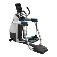
Precor AMT 885 Service Manual (400 pages)
Brand:
Precor
| Category:
Elliptical Trainer
| Size: 8.75 MB
Table of Contents
Table of Contents
3
Precor Incorporated, Unauthorized Reproduction and Distribution Prohibited by Law
8
About this Document
9
Acrobat Reader Users
9
Things You Should Know
10
Right, Left, Front, and Back Conventions
10
Figure 1: Front, Back, Left, Right Conventions
10
General System Information
11
Warning and Caution Statements and General Safety Guidelines
11
Safety
12
General Information
13
Tools Required
13
P30 Console
14
Accessing the P30 Diagnostic Software
15
Procedure
15
Figure 2: P30 Software Access
15
P30 Diagnostic Software Menu Table
16
Displaying P30 Information
21
Procedure
21
P30 Information Table
22
Setting the P30 Club Parameters
26
P30 Setting Club Parameters Table
26
Documenting P30 Software Problems
29
Replacing the Upper PCA
30
Figure 3: Dash Transition Cover - (TRM Only)
30
Figure 4: Console Mounting Plate
31
Figure 5: Console Access Panel
31
Figure 6: Maintenance Access Hook
32
Figure 7: P30 Cable Connectors
33
Figure 8: Option Cap Back Cover
34
Figure 9: Rear Console Cover
34
Figure 10: P30 Upper PCA & Metric Board
35
Figure 11: P30 PCA - Pin 1 Reference
36
Replacing the P30 Metrics PCA
37
Figure 12: P30 Upper PCA & Metric Board
38
Replacing the P30 HR PCA
39
Figure 13: HR PCA Access Panel
40
Flash Programming the Upper PCA
41
Figure 14: HHHR Cable Assembly
41
Upload Procedure
42
P30 Troubleshooting
43
Troubleshooting the Keypad and Upper PCA
43
Procedure
43
Figure 15: Upper PCA , Option Cap (J6) Connector
44
Figure 16: Metrics PCA, Front View
45
Troubleshooting the Handheld Heart Rate
46
Circuit Description
46
Normal Hand Held Reading - no Chest Strap Reading
47
No Hand Held Reading - Normal Chest Strap Reading
47
Figure 17: Hand Held - Chest Strap Heart Rate PCA
47
No Hand Held Reading - no Chest Strap Reading
49
P30 AMT '11 - Upper Display Does Not Illuminate
50
Figure 18: Lower PCA Test Points
51
P80 Console
52
P80 Settings
53
Figure 19: P80 Console
53
Figure 20: P80 Sign in Access
54
P80 Settings Table
55
P80 about
56
About P80 Table
57
P80 Equipment Usage
59
P80 Equipment Usage Table
60
P80 System Settings
60
P80 System Settings Table
62
Updating P80 Software
63
Figure 21: P80 Sign in Access
64
Figure 22: P80 USB Flash Drive Port
64
P80 System Tests
65
P80 System Test Table
66
P80 Connectivity
72
P80 Connectivity Settings Table
73
P80 Connectivity Set up and Registration Procedure
73
Figure 23: Not Connected & Connected
74
Figure 24: IP Address Not Present
75
Figure 25: IP Address Connected
76
Figure 26: Connectivity Automatic
77
Figure 27: Configuration - Manual
78
Figure 28: Network Settings
79
P80 Display
80
P80 Display Settings Table
82
P80 TV Settings
83
Channel Guide
85
To Scan for Available Channels
85
To Name a Channel
85
To Delete a Channel from the Channel Guide
85
P80 Workout Limits
86
P80 Workout Limits Table
87
Manage P80 Settings (Cloning)
90
P80 Cloning Settings Table
91
P80 Cloning Procedure
91
Figure 29: P80 Sign in Access
92
Figure 30: Manage Settings (Cloning)
93
Figure 31: P80 USB Flash Drive Port
94
Figure 32: Cloning Procedure- Save to USB
94
Figure 33: Settings Exported Successfully
95
Figure 34: Import from USB
96
Figure 35: Settings Imported Successfully
96
Replacing the P80 Console
97
Console Mounting - Removal
97
Figure 36: P80 Rear Cover Removal
98
Figure 37: Console Mounting Screws
98
Disconnection Cables
99
Figure 38: Coax Cable
99
Console Hook and Notch
100
Figure 39: Disconnecting Cables
100
Cable Connections
101
Figure 40: Console Mounting Notch
101
Figure 41: Cable Connections
102
Figure 42: P80 Power Cable Routing
103
Console Mounting - Install
104
Replacing the P80 Heart Rate PCA Board
104
Figure 43: P80 Heart Rate Cable Routing
104
Figure 44: P80 Rear Cover Removal
105
Figure 45: P80 Heart Rate PCA Board
106
P80 Troubleshooting
108
Black Screen - TV Only
108
Description
108
Possible Causes
108
Possible Remedies
109
Figure 46: Coax Cable & TV Tuner USB Cable
109
Black Screen - Full Console
111
Description
111
Possible Causes
111
Possible Remedies
111
Boot Screen Procedure
111
Poor Quality Video - Single Unit Only
112
Description
112
Possible Causes
112
Possible Remedies
112
Poor Quality Video - All Units
113
Description
113
Possible Causes
113
Possible Remedies
114
Poor Quality Video - One Channel or Limited Channels
114
Green Screen
115
Description
115
Possible Causes
115
Stuttering Channels
115
Possible Causes
116
Possible Remedies
116
Touch Screen Unresponsive
116
Description
116
Single Secret Handshake Procedure
117
Procedure
117
Figure 47: P80 Sign in Access
117
Touch Screen Slow Response
118
Description
118
Possible Causes
118
Possible Remedies
118
Touch Screen Responses Incorrectly to Touch
118
Possible Remedies
119
Single Secret Handshake Procedure
119
Procedure
119
Poor Audio Quality - All Channels, One/Limited Units
120
Description
120
Possible Causes
120
Figure 48: P80 Sign in Access
120
Possible Remedies
121
Poor Audio Quality - All Channels, Multiple Units
121
Description
121
Possible Causes
121
Machine Controls Unresponsive
122
Description
122
Possible Causes
122
Possible Remedies
122
Machine Controls Incorrect Response
123
Description
123
Possible Causes
123
Possible Remedies
123
Message out of Service Displayed
124
Description
124
Possible Causes
124
Possible Remedies
124
Message Please Reset the Treadmill Displayed
124
Possible Causes
125
Possible Remedies
125
Unit Reboots of Its Own Volition
125
Description
125
Possible Remedies
126
Checking the AMT Operation
127
Checking AMT Operation
127
Procedure
127
Inspection and Adjustment Procedures
129
Measuring the Resistance of a Generator
129
Procedure
129
Figure 49: Battery
130
Inspecting and Adjusting the H-Brake Belt Tension
131
Procedure
131
Figure 50: H-Brake Belt Tension Gauge
131
Inspecting and Adjusting the Generator Belt Tension
132
Figure 51: H-Brake Belt and H-Brake Cam
132
Figure 52: Generator Belt
133
Procedure
133
Inspecting and Adjusting the Drive Input Belt Tension
134
Procedure
134
Figure 54: Dive Input Belt
135
Figure 55: Generator
136
Figure 56: Step up Pulley
137
Figure 57: Generator Belt
138
Calibrating the Incline Motor
139
Procedure
139
Figure 58: Generator
139
Figure 59: Gas Shock
140
Figure 60: Incline Motor Hitch Pin and Mounting Pin
141
Figure 61: Incline Motor Calibration Measurement
142
Figure 62: Gas Shock
143
Drive Belt Gauge Instructions
144
Preventive Maintenance
146
Regular Preventive Maintenance (Owner)
146
After each Use
146
Daily Maintenance
146
Weekly Maintenance
147
Quarterly Maintenance
147
On-Site Preventive Maintenance (Service Technician)
148
AMT Base Troubleshooting Procedures
149
Troubleshooting the Generator
149
Troubleshooting the Incline System
150
Figure 63: Lower PCA Fuse Locations
151
Troubleshooting the Interconnect Cable
152
AMT Base Replacement Procedures
154
Cover Replacement
154
Top Cover Removal
155
Figure 64: Front, Back, Left, Right Conventions
155
Figure 65: Cover Gasket
155
Front Cover Removal
156
Figure 66: Front Top Cover Release
156
Figure 67: Top Cover
156
Figure 68: Front Cover - Screw Locations
157
Figure 69: Side Cover Markers and Front Cover
157
Center Beam Cover Removal
158
Back Cover Removal
158
Figure 70: Center Beam Cover Removal
158
Left and Right Side Cover Removal
159
Left and Right Side Bottom Cover Removal
159
Figure 71: Back Cover Removal
159
Figure 72: Side Cover Removal
159
Left and Right Bottom Cover Assembly
160
Left and Right Side Cover Assembly
160
Figure 73: Left and Right Side Cover Screw Locations
160
Figure 74: Bottom Covers Removed
160
Back Cover Assembly
161
Figure 75: Side Cover Assembly
161
Figure 76: Back and Bottom Cover Assembly
161
Center Beam Cover Assembly
162
Figure 77: Back Cover Locking Tab
162
Front Cover Assembly
163
Upper Arm Cover Replacement
163
Figure 78: Upper Arm Covers
163
Rear Flat Belt Terminal Cover Replacement
164
Figure 79: Upper Arm Cover Screw Locations
164
Upper Arm Cam Cover Replacement
165
Figure 80: Flat Belt Terminal Covers
165
Figure 81: Upper Arm Cam Covers
165
Top Cover Assembly
166
Replacing a Belt Guard
166
Finger Guard Replacement Procedure
166
Figure 82: Upper Arm Covers
166
Figure 83: Upper Arm Cover Screw Locations
167
Figure 84: Belt Guard and Upper Arm
168
Figure 85: Belt Guard Removal
168
Figure 86: Belt Guard Interlocking Tabs and Slots
169
Replacing the Upper Arm Grip
170
Upper Arm Grip Replacement Procedure
170
Figure 87: Belt Guard Mounting
170
Figure 88: Upper Arm Covers
171
Figure 89: Upper Arm Cover Screw Locations
172
Figure 90: Belt Guard and Upper Arm
173
Figure 91: Belt Guard Removal
174
Figure 92: Upper Arm Grip Screw Locations
175
Figure 93: Upper Arm Grip Removal
176
Replacing a Flat Belt Terminal
177
Flat Belt Terminal Replacement Procedure
177
Rear Flat Belt Terminal Cover Removal
177
Figure 94: Belt Guard Interlocking Tabs and Slots
177
Figure 95: Flat Belt Terminal Covers
178
Figure 96: Flat Belt Clamp and Flat Belt Terminal
178
Figure 97: Flat Belt Terminal Removal
179
Figure 98: Stairarm Height Measurement
180
Figure 99: Flat Belt Terminal Adjustment
180
Replacing a Upper Arm Flat Belt Pulley
181
Upper Arm Flat Belt Pulley Replacement Procedure
181
Figure 100: Flat Belt Terminal Covers
181
Figure 101: Upper Arm Covers
182
Figure 102: Upper Arm Cover Screw Locations
183
Figure 103: Belt Guard and Upper Arm
184
Figure 104: Belt Guard Removal
185
Figure 105: Upper Arm Flat Belt Pulley Mounting
185
Figure 106: Upper Arm Flat Belt Pulley Removed
186
Figure 107: Belt Guard Interlocking Tabs and Slots
187
Replacing a Stairarm Pedal
188
Figure 108: Upper Arm Cover Screw Locations
188
Figure 109: Stairarm and Stairarm Pedal
189
Stairarm Pedal Replacement Procedure
189
Replacing a Stairarm
190
Figure 110: Stairarm and Stairarm Pedal Screw Locations
190
Figure 111: Stairarm and Front Arm
191
Rear Flat Belt Terminal Cover Removal
191
Stairarm Replacement Procedure
191
Figure 112: Flat Belt Terminal Covers
192
Figure 113: Flat Belt Terminal Removal
192
Figure 114: Stairarm and Front Arm Screw Locations
193
Figure 115: Stairarm and Stairarm Pedal Screw Locations
194
Figure 116: Stairarm Knuckle Cover Screw Locations
194
Figure 117: Stairarm and Stairarm Pedal Screw Locations
195
Figure 118: Flat Belt Terminal Removal
196
Replacing the Flat Belts
197
Figure 119: Flat Belt Terminal Covers
197
Figure 120: Flat Belts
198
Belt Replacement & Odometer Tracking Codes
200
Figure 121: Front Belt Clamps
201
Inside Flat Belt Replacement
201
Figure 122: Front Belt Clamp Screw Removal
202
Figure 123: Upper Arm Cam Covers
203
Figure 124: Upper Inside Cam Screw Removal
203
Figure 125: Upper Inside Cam Pin Removal
204
Figure 126: Flat Belt End Measurement
204
Figure 127: Upper Inside Cam Flat Belt Routing
205
Figure 128: Upper Inside Cam Pin Install
206
Figure 129: Inside Flat Belt Routing
207
Figure 130: Front Flat Belt Clamp Pin Mounting
208
Figure 131: Flat Belt End Alignment
209
Figure 132: Upper Arm Covers
210
Outside Flat Belt Replacement
210
Figure 133: Upper Arm Cover Screw Locations
211
Figure 134: Belt Guard and Upper Arm
212
Figure 135: Belt Guard Removal
212
Figure 136: Upper Arm Grip Screw Locations
213
Figure 137: Upper Arm Grip Removal
214
Rear Flat Belt Terminal Cover Removal
214
Figure 138: Flat Belt Terminal Covers
215
Figure 139: Flat Belt Removal - Terminal
215
Figure 140: Flat Belt Pin Removal
216
Figure 141: Upper Arm Flat Belt Pulley Mounting
217
Figure 142: Upper Arm Flat Belt Pulley Removed
218
Figure 143: Upper Outside Cam Screw Removal
219
Figure 144: Upper Outside Cam Pin Removal
219
Figure 145: Flat Belt Routing - Transparent View of Arm
220
Figure 146: Outside Flat Belt Routing - Cam
221
Figure 147: Upper Outside Cam Pin
222
Figure 148: Flat Belt Terminal Pin
223
Figure 149: Outside Flat Belt Alignment
224
Figure 150: Stairarm Height Measurement
225
Figure 151: Flat Belt Terminal Adjustment
225
Figure 152: Belt Guard Interlocking Tabs and Slots
226
Figure 153: Upper Arm Cover Screw Locations
227
Replacing the Front Arm Assemblies - with Flat Belts and Press Fit Cams (after 4/3/2013)
228
Figure 154: Cover Gasket
228
Figure 155: Front Top Cover Release
229
Figure 156: Top Cover
229
Figure 157: Front Cover - Screw Locations
230
Figure 158: Left and Right Side Cover Screw Locations
232
Figure 159: Bottom Covers Removed
233
Figure 160: Upper Arm Cam Covers
233
Figure 161: Flat Belt Terminal Covers
234
Rear Flat Belt Terminal Cover Removal
234
Figure 162: Flat Belt Clamp and Flat Belt Terminal
235
Figure 163: Upper Arm Cover Screw Locations
236
Figure 164: Upper Arm Grip Screw Locations
237
Figure 165: Upper Arm Grip Removal
238
Figure 166: Belt Guard and Upper Arm
238
Figure 167: Belt Guard Removal
239
Figure 168: Upper Arm Flat Belt Pulley Mounting
240
Figure 169: Upper Arm Flat Belt Pulley Removed
240
Figure 170: Front Belt Clamps
241
Front Flat Belt Terminal Removal
241
Figure 171: Stairarm and Front Arm Screw Locations
242
Figure 172: Tie Rods
242
Figure 173: Front Arm Mounting Bolt
243
Figure 174: Main Shaft Clamp Bolts
244
Figure 175: Front Arm and Belts
245
Figure 176: Flat Belt Routing - Transparent View of Arm
246
Figure 177: Front Arm Shaft and Main Clamp
246
Figure 178: Front Arm Mounting Bolt
247
Figure 179: Main Shaft Clamp Bolts- Torque Sequence
247
Figure 180: Belt Guard Interlocking Tabs and Slots
249
Figure 181: Stairarm and Front Arm Screw Locations
250
Figure 182: Flat Belts
250
Figure 183: Front Belt Clamps
251
Figure 184: Tie Rods
251
Figure 185: Stairarm Height Measurement
252
Replacing a Front Arm Assembly - Without Flat Belts and Non-Press Fit Cams. (Prior to 4/3/2013)
253
Figure 186: Flat Belt Terminal Adjustment
253
Front Arm and Cam Replacement Procedure
254
Figure 187: Stairarm and Front Arm Screw Locations
255
Figure 188: Upper Inside Cam Screw Removal
256
Figure 189: Upper Inside Cam Pin Removal
256
Figure 190: Tie Rods
257
Figure 191: Front Arm Mounting Bolt
258
Figure 192: Main Shaft Clamp Bolts
258
Figure 193: Front Arm Cam Orientation
259
Figure 194: Flat Belt Cam Screws & Cam Screws
260
Figure 195: Front Arm and Cam Square Keys
261
Figure 196: Front Arm Shaft and Main Clamp
262
Figure 197: Main Shaft Clamp Bolts- Torque Sequence
262
Figure 198: Front Arm Mounting Bolt
263
Figure 199: Tie Rods
263
Figure 200: Flat Belt End Measurement
264
Figure 201: Upper Inside Cam Flat Belt Routing
265
Figure 202: Upper Inside Cam Pin Install
266
Figure 203: Outside Flat Belt Routing - Cam
266
Figure 204: Outside Flat Belt Routing - Cam
268
Figure 205: Upper Outside Cam Pin
269
Replacing the Lower Board
270
Removing the Lower PCA Cover
270
Replacing the Front Arm Assemblies - with Flat Belts and Press Fit Cams
270
Figure 206: Stairarm and Front Arm Screw Locations
270
Removing the Lower PCA
271
Figure 207: Lower PCA Cover
271
Replacing the Lower PCA and Battery Bracket
272
Procedure
272
Figure 208: Lower PCA
272
Figure 209: Lower PCA and Battery Bracket
273
Figure 210: Lower PCA & Battery Bracket Mounting
273
Replacing the Battery
274
Procedure
274
Replacing the Generator Belt
275
Procedure
275
Figure 211: Battery
275
Figure 53: Generator
276
Figure 212: Generator
276
Figure 213: Dive Input Belt
277
Figure 214: Step up Pulley
278
Figure 215: Generator Belt
279
Replacing the Generator
280
Procedure
280
Figure 216: Generator
280
Figure 217: Generator
281
Figure 218: Generator Belt
282
Replacing the Drive Input Pulley Belt
283
Drive Input Pulley Belt Replacement Procedure
283
Figure 219: Generator
283
Figure 220: Dive Input Belt
284
Figure 221: Step up Pulley
285
Figure 222: Generator Belt
286
Replacing the Step up Pulley
287
Procedure
287
Figure 223: Generator
287
Figure 224: Generator
288
Figure 225: Step up Pulley
289
Figure 226: Dive Input Belt
290
Figure 227: Step up Pulley
291
Figure 228: Generator Belt
292
Replacing the Crank Arm
293
Crank Arm Replacement Procedure
293
Figure 229: Generator
293
Figure 230: Crank Arm Alignment
294
Figure 231: Crank Arm Bolt Removal/ Installation
295
Figure 232: Crank Arm Flat Belt Pulley
295
Figure 233: Crank Arm Alignment
296
Figure 234: Crank Arm Bolt Removal/ Installation
297
Figure 235: Crank Arm Flat Belt Pulley
297
Replacing the Drive Input Pulley
298
Procedure
298
Figure 236: Generator
298
Figure 237: Step up Pulley
299
Figure 238: Crank Arm Flat Belt Pulley
300
Figure 239: Crank Arm Bolt Removal/ Installation
301
Figure 240: Drive Input Assembly
302
Figure 241: Drive Input Assembly Alignment
302
Figure 242: Crank Arm Alignment
303
Figure 243: Crank Arm Bolt Removal/ Installation
304
Figure 244: Crank Arm Flat Belt Pulley
304
Figure 245: Dive Input Belt
305
Figure 246: Step up Pulley
306
Figure 247: Generator Belt
307
Replacing the Lift Arm Housing
308
Lift Arm Housing Replacement Procedure
308
Figure 248: Generator
308
Figure 249: Generator
309
Figure 250: Step up Pulley
310
Figure 251: Gas Shock
311
Figure 252: Incline Motor Hitch Pin and Mounting Pin
312
Figure 253: Incline Motor Mounting
313
Figure 254: Crank Arm Flat Belt Pulley
313
Figure 255: Crank Arm Bolt Removal/ Installation
314
Figure 256: Drive Input Flat Belt Pulley
315
Figure 257: Drive Input Assembly
315
Figure 258: Drive Input Assembly Alignment
316
Figure 259: Lift Arm and Belt Clamps
316
Figure 260: Lift Arm Mounting Bolts
317
Figure 261: Lift Arm Housing and Drive Input Housing
317
Figure 262: Drive Input Assembly Alignment
318
Figure 263: Crank Arm Alignment
319
Figure 264: Crank Arm Bolt Removal/ Installation
320
Figure 265: Crank Arm Flat Belt Pulley
320
Figure 266: Dive Input Belt
321
Figure 267: Step up Pulley
322
Figure 268: Generator Belt
323
Figure 269: Generator
324
Figure 270: Incline Motor Mounting
325
Figure 271: Incline Motor Calibration Measurement
326
Replacing the Drive Input Housing
327
Drive Input Housing Replacement Procedure
327
Figure 272: Gas Shock
327
Figure 273: Generator
328
Figure 274: Step up Pulley
329
Figure 275: Gas Shock
330
Figure 276: Incline Motor Hitch Pin and Mounting Pin
331
Figure 277: Incline Motor Mounting
332
Figure 278: Crank Arm Flat Belt Pulley
332
Figure 279: Crank Arm Bolt Removal/ Installation
333
Figure 280: Drive Input Flat Belt Pulley
334
Figure 281: Drive Input Assembly
334
Figure 282: Drive Input Assembly Alignment
335
Figure 283: Lift Arm and Belt Clamps
335
Figure 284: Lift Arm Mounting Bolts
336
Figure 285: Lift Arm Housing and Drive Input Housing
336
Figure 286: Lift Arm Housing and Drive Input Housing
337
Figure 287: Drive Input Assembly Alignment
337
Figure 288: Lift Arm Mounting Bolts
338
Figure 289: Drive Input Assembly Alignment
338
Figure 290: Crank Arm Alignment
339
Figure 291: Crank Arm Bolt Removal/ Installation
340
Figure 292: Crank Arm Flat Belt Pulley
340
Figure 293: Dive Input Belt
341
Figure 294: Step up Pulley
342
Figure 295: Generator Belt
343
Figure 296: Generator
344
Figure 297: Incline Motor Mounting
345
Figure 298: Incline Motor Calibration Measurement
346
Replacing a Tie Rod
347
Procedure
347
Figure 299: Gas Shock
347
Replacing the Stride Dial Sensor
348
Procedure
348
Figure 300: Tie Rods
348
Figure 301: Stride Dial Assembly
349
Replacing the H-Brake Belt
350
Figure 302: Stride Dial Assembly
350
Figure 303: H-Brake Belt and H-Brake Cam
350
Figure 304: H-Brake Belt Assembly
351
Procedure
351
Replacing the H-Brake Cam Assembly
352
Figure 305: H-Brake Belt Tension Gauge
352
Figure 306: H-Brake Belt and H-Brake Cam
353
Figure 307: H-Brake Belt Assembly
353
Procedure
353
Figure 308: Stride Dial Assembly
354
Figure 309: Tie Rods
355
Figure 310: Cam Assembly
355
Figure 311: Tie Rods
356
Figure 312: Stride Dial Assembly
357
Replacing the H-Brake Drum Assembly
358
Procedure
358
Figure 313: H-Brake Belt Tension Gauge
358
Figure 314: H-Brake Belt Assembly
359
Figure 315: Gas Shock
360
Figure 316: Incline Motor Hitch Pin and Mounting Pin
361
Figure 317: Incline Motor Mounting
362
Figure 318: H-Brake Assembly
363
Figure 319: H-Brake Drum - Units Built after 10-1-1012
364
Figure 320: Incline Motor Mounting
364
Figure 321: Incline Motor Calibration Measurement
365
Figure 322: Gas Shock
366
Replacing the Gas Shock
367
Figure 323: H-Brake Belt Tension Gauge
367
Figure 324: Gas Shock
368
Figure 325: Incline Motor Hitch Pin and Mounting Pin
369
Replacing the Incline Motor
370
Procedure
370
Figure 326: Gas Shock
371
Figure 327: Incline Motor Hitch Pin and Mounting Pin
372
Figure 328: Incline Motor Flat Belt Pulley
372
Figure 329: Incline Motor Mounting
373
Figure 330: Incline Motor Calibration Measurement
374
Figure 331: Gas Shock
375
Wiring Diagrams
376
P30 - AMT '11 835 Block Diagram
377
P20_P30_P80 AMT '11 Wiring Diagram
381
Index
397
Advertisement
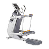
Precor AMT 885 Assembling And Maintaining Manual (100 pages)
Adaptive Motion Trainers
Brand:
Precor
| Category:
Fitness Equipment
| Size: 4.56 MB
Table of Contents
Table of Contents
16
Important Safety Instructions
7
Safety Precaution S
7
Educating Users
10
Hazardous Materials and Proper Disposal
10
Product Recycling and Disposal
10
Regulatory Notices for the RFID Module
11
European Applications
12
Regulatory Notices for Cardiovascular Exercise Equipment
13
Electrical Recommendations: All Equipment Excluding Treadmills
15
Obtaining Service
15
Obtaining Updated Documentation
15
Table of Contents
16
Assembling the AMT
21
Required Tools
21
Performing the Assembly
21
Removing Access Covers
24
Threading the Cables
24
Replacing Access Covers
26
Leveling the AMT
26
Breaking in the Equipment
28
Installing the Console
31
Connecting Cables (P80)
31
Completing the Console Installation (P80)
35
Threading the Cable Assembly (P30)
35
Connecting Cables (P30)
37
Completing the Console Installation (P30)
38
Verifying that the Heart Rate Display Is Operational
38
Maintenance
39
Daily Cleaning
39
Daily Inspection
40
Weekly Maintenance
41
Monthly Maintenance
41
Storing the Chest Strap
42
Moving the Equipment
42
Long-Term Storage
42
Self-Powered Features
43
Informational Displays Prior to Shutdown
44
Symptoms of a Low Battery
44
Using the Optional Power Adapter
44
The Optional Power Adapter Kit
45
Replacing the Battery
45
Commercial Cardiovascular Equipment Limited Warranty
47
Exclusive Remedies
49
Important Safety Instructions
57
Safety Precautions
57
Table of Contents
65
Getting Started
67
Activating the Console for Self-Powered Equipment
67
Identifying Parts of the Console
69
Setting up the Console
73
System Settings
73
Setting Club Parameter Values
75
Viewing the Informational Displays
80
User ID Entry with CSAFE Equipment
83
Introducing Users to the P30 Console
85
Using the Touch Heart Rate Feature
85
Using a Chest Strap Transmitter
87
Using the Treadmill Safety Clip
88
Treadmill Auto Stop™ (Automatic Stop) Function
90
Starting a Workout
91
Starting a Preset Programmed Workout
92
Setting Options
92
Pausing and Resuming an Exercise Session
94
Ending a Session
95
Programs
97
Heart Rate
97
Weight Loss
98
Maintenance
99
Cleaning the Console and Display
99
Precor AMT 885 Assembly Manual (45 pages)
Brand:
Precor
| Category:
Fitness Equipment
| Size: 10.12 MB
Table of Contents
Assembly Guide
8
Monthly Maintenance Tasks
38
Quarterly Maintenance Tasks
39
Error Codes
40
Moving the Equipment
41
Advertisement
Advertisement
Related Products
Precor AMT 835
Precor AMT 800-Series
Precor AMT12 base
Precor AMT 883
Precor AMT800-16 Base
Precor AMT700-16 Base
Precor AMT800-18 Base
Precor AMT700-18 Base
Precor Ab-X100
Precor AMT 813
Precor Categories
Fitness Equipment
Elliptical Trainer
Treadmill
Exercise Bike
Music Mixer
More Precor Manuals
Login
Sign In
OR
Sign in with Facebook
Sign in with Google
Upload manual
Upload from disk
Upload from URL