Sign In
Upload
Manuals
Brands
Polaris Manuals
Offroad Vehicle
1996 Xpress 400
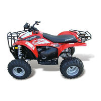
Polaris 1996 Xpress 400 Utility Quad Manuals
Manuals and User Guides for Polaris 1996 Xpress 400 Utility Quad. We have
1
Polaris 1996 Xpress 400 Utility Quad manual available for free PDF download: Service Manual
Polaris 1996 Xpress 400 Service Manual (634 pages)
Polaris ATV And Light Utility Vehicle Service Manual
Brand:
Polaris
| Category:
Offroad Vehicle
| Size: 48.29 MB
Table of Contents
Safety Labels and Instructions
2
Table of Contents
3
General Information
5
Table of Contents
5
Model Identification
6
Engine Serial Number Locationi
6
Transmission ID Number Location
6
Carburetor ID Number Location
6
1996 Model Identification
7
Vehicle Identification Number (1997 and Later Model Years)
8
1996 Publication Numbers
10
1997 Publication Numbers
10
1998 Publication Numbers
11
Service Traning Videos
11
Service/Information Bulletins
12
Bulleting Index - 1996 by Model
13
Bulleting Index - 1997 by Model
14
Bulleting Index - 1998 by Model
14
1997 Paint Codes
16
Specifications 1997
18
Specifications 1998
23
Standard Torque Specifications
26
Decimal Equivalents
27
Conversion Table
28
Tap Drill Charts
29
SAE Tap Drill Sizes
29
Metric Tap Drill Sizes
29
Warranty
30
Service Tips
31
Glossary of Terms
32
Special Tools
35
Routing Diagrams
36
Magnum Routing Diagram
36
Hoses Diagram
39
300 Fan Motor Wiring Diagram
40
Wire Harness Diagram
41
Chassis/Suspension Service Tools
42
Transmission Tool Kit - Shaft Drive
42
Yoke Gauge Tool - Shaft Drive
42
Mity Vac Pump Kit
43
Small Battery Hydrometer
43
Transmission Seal/Bearing Driver - 50 MM
43
CV Boot Clamp Pliers
43
Glossary (2)
45
Magnum Routing Diagram (Cont.)
48
Hosed Diagram (2)
51
300 Fan Motor Wiring Diagram (2)
52
Wire Harness Diagram (2)
53
Oil Tank Vent Line Routing (1996 Sportsman 500) Diagram
54
Maintenance
56
Periodic Maintenance Chart
58
Pre-Ride/Daily Inspection
59
Recommended Lubricants and Capacities
60
Lubrication Chart
62
Lubrication Chart - Type IV Transmission (Shaft Drive)
65
Front Gearcase Lubrication
67
Gearcase Lubricant Change
67
Carburetor Adjustments
68
Idle Speed Adjustment
68
Throttle Cable/Electronic Throttle Control ETC Switch Adjustment
68
Throttle Operation
68
Throttle Cable Adjustment
69
Choke Adjustments
69
Throttle Control Lever Stop Adjustment
69
Air Screw Adjustment - 2-Stroke Models
70
Pilot Screw (Idle Mixture) Adjustment - 4-Stroke Models
70
Fuel Lines
72
Vent Lines
72
Fuel Filter
72
Carburetor Float Bowl Draining
72
Carburetor Draining
73
Breather System (4 Strokes)
74
Breather Filter Inspection
74
Breather Hose
74
General Maintenance
76
Compression Test
76
Battery Maintenance
77
Spark Plug Maintenance
78
Ignition Timing
78
Engine Mounts
78
Coolant Level Inspection
79
Coolant Strength
79
Cooling System Pressure Test
79
Radiator
79
Oil Pump Adjustment Procedure
80
Oil Pump Bleeding Procedure
83
If Oil Starvation Is Suspected
83
Recoil Housing
84
Counter Balancer Lubrication (400)
84
Procedure for Adding Oil (400)
84
Counter Balance Oil Changing Procedure
84
Air Cleaner - Trail Boss, Xpress 300, Xplorer 300, Xplorer 400
85
Dual Stage Air Cleaner
85
Primary Pre-Cleaner Foam Boot
85
Secondary (Main) Filter
86
Secondary Filter Removal and Installation Procedure
86
Cleaning the Main Filter
86
Air Filter Service -Sport, Scrambler 400
87
Air Filter Service - Trail Blazer
88
2 Stroke Engine Maintenance
89
Oil Filter (2 Strokes)
89
4 Stroke Engine Maintenance
90
Air Filter - 4 Stroke Engine
92
Pre-Filter Service
92
Air Filter Main Element
92
Air Box Sediment Tube
93
Air Filter Service - Scrambler 500
94
Air Filter Service - Sportsman 500, Xplorer 500
94
Check Engine Oil (4 Stroke)
96
Oil and Filter Change (4 Stroke)
96
Engine Sump Drain Plug View
97
Valve Clearance
100
Intake Valve Clearance Adjustment
101
Exhaust Valve Clearance Adjustment
101
Throttle Cable Lubrication
102
Toe Alignment Inspection
103
Chassis Maintenance
104
Steering Maintenance
104
Camber and Caster Adjustment
104
Toe Alignment Inspection (Chassis Maintenance)
104
The Rod End Inspection
105
Front Hubs (4X4 AWD Model)
105
Changing Front Hub Fluid
105
Exhaust Pipe
106
Brake System Inspection
107
Brake Fluid Level Inspection
107
Wear Line
107
Auxiliary Mechanical Brake System
108
Auxiliary Brake Testing
108
Auxiliary Brake Adjustment
108
Hose/Fitting Inspection
108
Drive Chain and Sprocket Inspection
109
Rear Drive Chain Note
109
Drive Chain Inspection
109
Rear Drive Chain Tension Adjustment
110
Drive Chain Adjustment, Concentric Swingarm
111
Center/Front Drive Chain Slack Adjustment
113
Center/Front Drive Chain Inspection/Adjustment
113
Sprocket Inspection
113
Drive Chain Inspection/Adjustment
114
Rear Axle (6X6 Middle Axle) Adjustment Procedure
114
Final Drive Chain
114
6X6 Rear Axle Drive Chain Adjustment
114
Front Suspension
115
Rear Suspension
115
Controls Check
115
Transmission Lubrication
116
Transmission Oil Changing Procedure
116
Transmission Oil Change - Dipstick Models
116
Transmission Lubrication - Type V Shaft/Chain
117
Transmission Oil Change Procedure
117
Transmission Vent Line Routing
118
Transmission Linkage Adjustment
118
Wheels Inspection
119
Wheel, Hub, and Spindle Torque Table
119
Wheel Removal Front or Rear
119
Wheel Installation
119
Tire Pressure
120
Tire Tread Depth
120
Frame, Nuts, Bolts, Fasteners
120
Engine
122
2 Stroke Engine Torque Specifications
124
4 Stroke Engine Torque Specifications
124
Engine Fastener Torque Patterns
125
1996 To Current Engine Specifications
126
Piston Identification
126
EC38PL Engines
127
Jetting Guidelines for Round-Port Pistons
127
EH42PL/EH50PL Engine Service Data
129
Cooling System
131
System Pressure Test
131
Radiator Cap Pressure Test
131
Recommended Coolant
132
Cooling System Specifications
132
2 Stroke Engine Removal
133
Engine Removal Preparation, Typical (2 Stroke)
133
Engine Installation Notes (2 Stroke)
136
Bleed Cooling System
136
Transmission Readjustment
136
Engine Break in Period (2 Strokes)
136
EC25PF/EC28PF Engines Disassembly
137
Crankshaft Alignment
138
EC25PF/EC28PF Engines Assembly
139
Measure Crankshaft Width - Bearings Installed
139
Connecting Rod Side Clearance
140
EC25PF/EC28PF Engines Installation
144
Oil Pump End Play Adjustment
145
Oil Check Valve Testing (250/400)
146
Oil Check Valve Testing (300)
146
EC25PF Engine - Recoil Disassembly
147
EC25PF Engine - Recoil Assembly
148
EC38PL Engine Disassembly
150
Water Pump Impeller Clearance
156
Cylinder Hone Selection/Honing Procedure
158
Piston/Cylinder Clearance (2 Strokes)
159
Cylinder Inspection/Measurement
159
Piston Inspection/Measurement (Generic)
159
Piston Ring Installed Gap
160
Piston Pin/Needle Bearing Inspection
160
Connecting Rod Small End Inspection
161
EH42PL/EH50PL Engine Exploded View
162
EH42PL/EH50PL Lubrication/Oil Flow
163
Oil Pressure Test
163
EH42PL/EH50PL Engine Diagram
164
EH42PL/EH50PL Oil Flow Chart
164
EH42PL/EH50PL Engine Removal
165
Cylinder Head Bolts
165
Crankcase
165
AWD Models
166
PVT Disassembly, All Models
166
Recoil/Starter Removal
167
Final Coolant Draining/Engine Removal
169
EH42PL/EH50PL Engine Installation
170
Oil Supply
170
EH42PL/EH50PL Engine: Bleed Cooling System
170
Cam Chain Tensioner/Rocker Arm/Camshaft Removal
170
To Position Crankshaft at Top Dead Center (TDC) on Compression Stroke
171
Cam Chain Tensioner
171
Rocker Arm/Shaft Removal
172
Rocker Arm/Shaft Inspection
172
Camshaft Removal
174
Automatic Compression Release Removal/Inspection
175
Automatic Compression Release Installation
175
Camshaft Inspection
176
Cylinder Head Removal
177
Cylinder Head Disassembly/Inspection
178
Cylinder Head Warpage
179
Cylinder Head Disassembly
179
Valve Inspection
181
Combustion Chamber
182
Valve Seat Inspection
182
Cylinder Head Reconditioning
182
Valve Guide Removal/Installation
182
Valve Seat Reconditioning
183
Cylinder Head Assembly
186
Valve Sealing Test
187
Cylinder/Piston Removal and Inspection
187
Piston Removal
188
Cylinder Inspection
189
Piston to Cylinder Clearance
190
Piston Ring Installed Gap (EH42PL/EH50PL)
192
Crankcase Disassembly
192
Starter Drive Removal/Inspection
193
Flywheel/Stator Removal/Inspection
194
Cam Chain/Tensioner Blade
194
Stator Plate
194
One Way Valve
195
Crankcase Separation
195
Oil Pump Removal/Inspection
196
Oil Pump Assembly
198
Counter Balancer Shaft Removal/Inspection
198
Crankshaft Removal/Inspection
199
Crankcase Bearing Inspection
200
Pump Shaft Oil Seal/Water Pump Mechanical Seal Removal
200
EH42PL/EH50PL Engine Assembly
201
Crankcase Assembly
201
End Play Inspection/Adjustment
201
Crankshaft
201
Counter Balancer
203
Pump Shaft
203
Pump Shaft Oil Seal Installation
203
Crankshaft, Counter Balancer and Oil Pump Installation
204
To Assemble the Crankcase
204
Water Pump Mechanical Seal Installation
205
Water Pump Mechanical Seal Removal - Engine Installed
205
Piston Installation
208
Cylinder Installation
209
Cylinder Head Installation
210
Cam Chain/Camshaft Installation
211
Camshaft Installation - Timing Method
212
Method 1 - Camshaft Timing with Stator Removed
213
Camshaft Installation - Timing Method 2
214
Method 2 Camshaft Timing Using Flywheel TDC Mark
215
Cam Chain Tensioner Installation
216
Stator, Flywheel and Starter Drive Installation
216
Rocker Shaft/Rocker Arm Assembly Installation
218
Thermostat Installation
218
Oil Pipes
218
Engine - Sealed Recoil
219
Recoil Disassembly/Inspection
219
Recoil Assembly
220
To Install a New Spring
220
To Reinstall an Old Spring
220
Spark Plug Fouling - 2 Stroke Engine
222
Spark Plug Fouling - 4 Stroke Engine
222
2 Stroke Engine Troubleshooting
223
Starter Motor
224
4 Stroke Engine Troubleshooting
225
Piston Damage Checklist - 2 Stroke Engines
227
Fuel System/Carburetion
228
Fuel System/Carburetion - 1996 Specifications
230
Jetting Guidelines
230
Jetting Compensation for Altitude and Temperature - 1996 Models
230
Fuel System/Carburetion - 1997 Specifications
234
Jetting Compensation for Altitude and Temperature (1997)
234
Fuel System/Carburetion - 1998 Specifications
235
1998 Trail Boss W98AA25C (Engine -EC-25PFE-10) - Specifications and Clutching and Jetting Guidelines for Altitude and Temperature
235
1998 Trail Blazer W98AA25C (Engine -EC-25PFE-11) - Specifications and Clutching and Jetting Guidelines for Altitude and Temperature
236
XPRESS 300 W98CA28C (Engine -EC-28PFE-12) - Specifications and Clutching and Jetting Guidelines for Altitude and Temperature
237
XLPORER 300 W98CC28C (Engine -EC-28PFE-02) - Specifications and Clutching and Jetting Guidelines for Altitude and Temperature
238
1998 XLPORER 400 W98CC38C (Engine -EC-38PFE-06) - Specifications and Clutching and Jetting Guidelines for Altitude and Temperature
239
1998 Sport 400 W98BA38C (Engine - EC-38PLE-07) - Specifications and Clutching and Jetting Guidelines for Altitude and Temperature
240
1998 Scrambler 400 W98BC38C (Engine - EC38PLE-09) - Specifications and Clutching and Jetting Guidelines for Altitude and Temperature
241
Magnum 2 X 2 W98AA42A (Engine - EH-42PLE-02) - Specifications and Clutching and Jetting Guidelines for Altitude and Temperature
242
Magnum 4 X 4 W98AC42A (Engine - EH-42PLE-02) - Specifications and Clutching and Jetting Guidelines for Altitude and Temperature
243
1998 Scrambler 500 W98BC50A (Engine - EH50PLE-04) - Specifications and Clutching and Jetting Guidelines for Altitude and Temperature
244
Sportsman 500 W98CH50A (W90CH50AB) (Engine - EH-50PLE-07) - Specifications and Clutching and Jetting Guidelines for Altitude and Temperature
245
1998 Big Boss 500 6X6 W98AE50A (Engine - EH50PLE-06) - Specifications and Clutching and Jetting Guidelines for Altitude and Temperature
246
Fuel System/Carburetion - Jet Part Numbers
247
Oil Tank and Fuel Tank Assembly - Gen II (Except Magnum)
248
Fuel Tank Assembly (Magnum)
249
Oil Tank and Fuel Tank Assembly (Gen III Typical)
250
Fuel Tank Assembly (Gen IV)
251
Fuel Tank Assembly - 500 Models (1997 Xplorer 500, Sportsman 500)
252
Fuel Flow Diagrams
253
Mikuni VM Carburetor Exploded Diagram
254
Carburetor Function
255
Float System
255
Component Functions
256
Pilot Jet
256
Pilot Air Screw
256
Air/Fuel Mixture Ratio
256
Jet Needle
257
Needle Jet
257
Throttle Opening Vs. Fuel Flow
257
Throttle Valve
258
Main Jet
258
Starter System - Closed Throttle
259
Pilot System (0-3/8 Throttle)
260
Slide Cutaway (1/8-3/8 Throttle)
261
Jet Needle/Needle Jet (3/8-3/4 Throttle)
262
Main System (3/4 to Full Throttle)
263
Component Effect Vs. Throttle Opening
264
Mikuni VM Fuel Delivery Chart
264
Mikuni VM Carburetor System Components
265
Venting Systems
265
Mikuni BST 34 Carburetor Exploded View
266
Venting Systems (Mikuni CV)
267
Mikuni CV Carb Operation
268
Pilot (Idle and Slow) Systems
269
Starter System (Choke or Enrichment)
269
Float System (Mikuni CV)
270
Main System (Mikuni CV)
270
Magnum Fuel Tank Removal
271
Carburetor Removal ( Mikuni CV)
272
Carburetor Disassembly - Mikuni CV
273
Carburetor Cleaning - Mikuni CV
276
Carburetor Assembly - Mikuni CV
279
Carburetor Assembly/Adjustment - Mikuni CV
280
Float Height Adjustment (Mikuni CV)
280
CV Carburetor Installation
282
Needle and Seat Pressure Test Mikuni CV
283
Inlet Needle and Seat
283
Fuel Level (Mikuni CV)
283
Float Bowl Draining
284
Fuel Pump Exploded View
286
Fuel Pump Testing
287
Fuel Pump Disassembly
287
Fuel Pump Inspection/Assembly
287
Fuel System/Carburetion Troubleshooting
288
Fuel Starvation/Lean Mixture
288
Rick Mixture
288
Poor Idle
288
Idle too Low
289
Erratic Idle
289
Body and Steering
290
Body and Steering - Torque Specifications and Special Tools
292
Body Styles
293
1996 Body Styles
293
1997 Body Styles
293
1998 Body Styles
293
Body Assembly Exploded View (Gen II - Typical)
295
Cover/Panel Removal (Gen II - Typical)
296
Cover/Panel Removal (Gen III - Typical)
297
Cover/Panel Removal (Gen IV - Typical)
298
Body Assembly Exploded View (Gen III - Typical)
299
Body Assembly Exploded View (Gen IV - Typical)
300
Body Assembly Exploded View (Gen IV - Headlight Pod)
301
Headlight Pod Service (Gen IV Typical) - Disassembly
302
Headlight Pod Service (Gen IV Typical) - Installation
303
Side Panel Removal (Gen IV - Typical)
304
Toe Alignment
305
Toe Alignment - Method 2
306
Typical Steering Assembly, Exploded View, Trail Boss 250
307
Steering Assembly, Exploded View, 2X4 Models (Except Trail Boss 250)
308
Steering Assembly, Exploded View, 4X4 and 6X6 Models
309
Steering Stop Adjustment
310
Rear Axle Bend
310
A-Arm Replacement
310
Rear Drive Axle, Hub and Wheel Assembly, - 2X4 and 4X4 (Except Sportsman 500)
311
Concentric Swingarm Rear Axle Assembly, Exploded View - 1998 Scrambler 400/500
312
Concentric Swingarm Exploded View 1998 Scrambler 400/500
313
Rear Drive Axle, Hub and Wheel Assembly - Shaft Drive Models
314
Rear Strut Stabilizer, 6X6 Models
315
Rear Swing Arm Weldment, 6X6 Models
316
Swing Arm and Rear Suspension Exploded View
318
Swing Arm Removal
319
Swing Arm Removal/Inspection
320
Swing Arm Assembly/Installation
321
Concentric Swingarm Removal/Disassembly
322
Concentric Swingarm Assembly/Installation
323
Strut Assembly - 400L AWD, Magnum AWD
324
Front Strut Weldment Replacement
325
Front Strut Cartridge Replacement
325
Strut Assembly - 2X4 Models
325
Front Strut Service
326
Front Strut Removal
326
Front Strut Installation
327
Front Strut Ball Joint Replacement
328
2X4 Hub Bearing Service
329
2X4 Front Hub Disassembly/Inspection
329
2X4 Front Hub Assembly
330
2X6 Hub Bearing Service
331
2X4 Front Hub Installation
331
Fox Shock Service
332
Foxtm Shock Service
333
Fox Shock Standard Valving Chart
339
1996 Optional Suspension Springs
340
1997 Optional Suspension Springs
341
1996 Paint Codes
342
1997 Paint Codes
343
Clutches
344
Clutch - Specifications
346
Clutch - Special Service Tools and Supplies
346
1996 Productoin Specifications
346
1996 Clutch Recommendations for Altitude
346
1997 Production Specifications
347
1997 Clutch Recommendations for Altitude
347
1998 Production Specifications
348
1998 Clutch Recommendations for Altitude
348
Shift Weights
349
Drive Clutch Spring Specifications
351
Clutches Overview
352
Relationship of Drive Clutch Weights and Spring in Maintaining Operating RPM
352
PVT System Indroduction
353
Drive Clutch Operation
353
Driven Clutch Operation
353
Clutch Maintenance
354
PVT Maintenance/Inspection
354
PVT Overheating
354
PVT Sealing and Ducting Components - Type I
354
PVT Sealing and Ducting Components - Type II
355
PVT Sealing and Ducting Components - Type III
356
PVT Sealing and Ducting Components - Type IV
356
Typical PVT Disassembly
358
PVT Assembly
359
Drive Belt Tension
361
Drive Belt Removal/Inspection
361
Clutch Alignment /Offset
362
Driven Clutch Disassembly
363
Driven Clutch Assembly
365
Drive Clutch - Springs Specifications Table
367
Drive Clutch Inspection
368
Spider Removal
368
Moveable Sheave Bushing Inspection
368
Drive Clutch Disassembly
369
Roller, Pin and Thrust Washer Inspection
369
Drive Clutch Assembly
371
Clutch Bushing Removal and Installation
372
Polaris Kit PN 2871226
372
Drive Clutch Moveable Sheave - Bushing Removal
372
Drive Clutch Moveable Sheave - Bushing Installation
373
Drive Clutch Cover - Bushing Removal
374
Drive Clutch Cover - Bushing Installation
375
Driven Clutch Moveable Sheave - Bushing Removal
376
Driven Clutch Moveable Sheave - Bushing Installation
378
Engine Braking System (EBS)
380
One-Way Clutch
380
Driven Clutch Spring
380
High Elevation Setup
380
EBS Exploded View
381
Drive Clutch Disassembly - EBS
382
Drive Belt Removal - EBS
382
One-Way Clutch Inspection (Drive Clutch)
382
Inspection of Moveable Sheave Bushing
383
Driven Clutch Disassembly - EBS
384
One-Way Clutch Preliminary Inspection (Driven)
384
Roller Pin Disassembly
385
Operation Guidelines for EBS Clutches
387
Clutches Troubleshooting
388
Final Drive
390
Final Drive Torque Specifications
392
Wheel, Hub, and Spindle Torque
392
Rolling Torque
392
Final Drive Exploded View
393
AWD Front Hub
393
Demand 4 Operation - AWD Models
394
Electricl Hub Engagement (4X4)
394
Front Hub Disassembly (4X4)
395
Hilliard Clutch Disassembly/Inspection
396
Hilliard Clutch Assembly Testing
397
Seal Sleeve Replacement
397
Strut Seal Sleeve Replacement
398
Magnetic Coil Replacement
399
Wheel Hub Seal Replacement
400
Strut Casting Seal Replacement
401
Drive Shaft Boot Replacement
402
Front Drive Shaft CV Joint Boot Replacement (4X4 Models)
402
Hub/Wheel Bearing Installation (4X4 Models)
403
Hublwheel Bearing Installation
403
Front Hub Bearing Adjustment (AWD Models)
404
Front Hub Bearing Adjustment (AWD Models Equipped with Cotter Pins)
405
Front Axle Identification
407
Front Drive Axle Removal
409
Front Drive Axle Installation
410
U-Joint Service
411
U-Joint Disassembly (Typical)
411
U-Joint Inspection
412
U-Joint Assembly (Typical)
412
2X4 Front Hub Disassembly and Inspection
414
2X4 Front Hub Assembl.
415
2X4 Front Hub Install.
416
Rear Axle Removal
417
Rear Axle Installation
419
6X6 Middle Axle Sprocket Service
422
6X6 Middle Axle Sprocket Removal
422
Brake Disc Hub Removal
425
Middle Axle Assembly
426
Rear Hub/Bearing Carrier Removal (Type IV Shaft Drive)
428
Rear Hub Disassembly (Shaft Drive)
430
Rear Hub Assembly (Shaft Drive)
431
Rear Hub Installation
432
Rear Drive Shaft Removal
433
Rear Drive Shaft Disassembly
434
Rear Drive Shaft Assembly
434
Rear Drive Shaft Installation
435
Rear Eccentric Removal
436
Rear Eccentric Disassembly
436
Rear Eccentric Assembly
437
Rear Eccentric Installation
439
Center Eccentric Removal
440
Center Eccentric Disassembly
441
Center Eccentric Assembly
441
Center Eccentric Installation
443
Front Eccentric Removal
445
Front Eccentric Assembly
447
Front Eccentric Installation
449
Front Gearcase Removal
451
Prop Shaft Removal
451
Front Gearcase Disassembly
452
Front Gearcase Assembly
455
Front Gearcase Installation
458
Concentric Swingarm Rear Axle Removal
460
Concentric Swingarm Rear Axle Assembly
461
Concentric Swingarm Rear Axle Installation
461
Concentric Swingarm Rear Axle Assembly, Exploded View
463
Transmission Service
464
Transmission Service - Torque Specifications
466
Transmission Service - Lubrication
466
Gear Ratios
467
Torque Stop/Shift Linkage Adjustment
468
Shift Linkage Rod End Positioning
470
Transmission Service - Troubleshooting
471
Gear Shift Selector Removal
472
Gear Shift Selector Disassembly
472
Gear Shift Selector Assembly
474
Gear Shift Selector Installation
475
Boot Replacement
475
Transmission Service - Type III, EZ-Shift Transmission
476
Transmission Removal (Typical)
476
Type III Transmission Exploded View
478
Type III Transmission Disassembly
479
Type III Transmission Assembly
480
Type III Transmission Installation
481
Type III, EZ Shift Transmission Installation
483
Type V EZ-Shift Transmission (1998 Scrambler 400/500) Removal
484
Type IV, Shaft Drive Transmission Removal
485
Type IV, Shaft Drive Transmission Disassembly
488
1996 - Early 1997 Type IV Shaft Drive Transmission Exploded View
496
Late 1997 Type IV Shaft Drive Transmission Exploded View
497
1997 (Late) - Current Tensioner Installation
498
Shaft Drive Transmission Assembly
499
Transmission Output Gear Backlash Adjustment
503
Shaft Drive Transmission Installation
509
Front Drive Housing Seal Removal (in Frame)
513
Front Drive Housing Seal Installation (in Frame)
513
Brakes
514
Brakes Specifications
516
Brakes - Torque Specifications
517
Hydraulic Brake System Operation
518
Fluid Replacement/Bleeding Procedure
519
Brake Bleeding - Fluid Change
519
Front Pad Replacement
521
Front Pad Removal
521
Front Pad Inspection
522
Front Pad Assembly
523
Output Shaft Brake Pad Replacement/Adjustment
525
Output Shaft Brake Pad Inspection
526
Output Shaft Brake Pad Assembly
527
6X6 Rear Brake Pad Replacement
528
6X6 Rear Brake Pad Removal
528
6X6 Rear Brake Pad Inspection
529
6X6 Middle Axle Brake Pad Assembly
530
Master Cylinder Disassembly
531
Master Cylinder Inspection
533
Master Cylinder Assembly
533
Master Cylinder Installation
535
Front Caliper Disassembly
536
Front Caliper Inspection
537
Front Caliper Disassembly
537
Front Caliper Assembly
538
Front Caliper Installation
538
Output Shaft Caliper Service (Auxiliary Brake) - Disassembly
540
Output Shaft Caliper Inspection
540
Output Shaft Caliper Reassembly
541
Output Shaft Caliper Installation
542
6X6 Rear Caliper Removal
543
6X6 Rear Caliper Inspection
543
6X6 Rear Caliper Assembly
545
Dual Hydraulic Brake Caliper Bleeding
546
Auxiliary Brake Adjustment (Hydraulic)
547
Free Play of the Brake Pedal
547
Brakes Troubleshooting
548
Electrical
550
Electrical - Special Tools
552
1996 Electrical Specifications
553
1997 Electrical Specifications
554
1998 Electrical Specifications
555
1996 Stator Resistance Specifications
556
Battery Type
556
1997 Stator Resistance Specifications
557
Flywheel Identification
558
Headlamp Service, Gen II
559
Headlight Adjustment (Gen II)
559
Headlight Lamp Replacement (Gen II)
559
Headlamp Service - Gen III
561
Headlight Adjustment (Gen III - Scrambler, Trail Blazer E.S. and Sport)
561
Adjustment - Trail Blazer E.S. and Sport
561
Headlight Lamp Replacement (Gen III)
561
Headlamp Service - Gen IV
563
High Beam Headlight Adjustment (Gen IV)
563
Headlight Lamp Replacement (Gen IV)
563
Headlight Housing Replacement (Gen IV)
563
Indicator Lamp Service
564
Taillight/Brakelight Lamp Replacement
564
Indicator Lamp Replacement (Gen II, Gen III and Gen IV)
564
Timing Check Procedures
565
Typical Ingnition Timing Curves
566
Crankshaft Degree to Piston Position Conversion Chart (2 Stroke Engines)
567
Components of EC25/28PL 150 Watt Alternator (Exploded View)
568
Components of EC38PL 150 Watt Alternator (Exploded View)
569
Components of EC38PL 200 Watt Alternator (Exploded View)
570
Components of EC42PL/EH50PL 200/250 Watt Alternator (Exploded View)
571
Ignition System
572
Cranking Output Test with Peak Reading Voltmeter
573
CDI Output Test Using Peak Reading Adaptor
573
Ignition System Troubleshooting
574
No Spark, Weak or Intermittent Spark
574
Battery Service
575
Battery Terminals/Terminal Bolts
575
Battery Inspection/Removal
576
Battery Installation
576
Battery Testing
576
OCV - Open Circuit Voltage Test
576
Specific Gravity Test
577
Load Test
577
Off Season Storage
578
Charging Procedure
578
Charging System Testing
579
Current Draw - Key off
580
Charging System "Break Even" Test
580
Alternator Ouptut Test (AC Amp)
580
Starter System Troubleshooting
581
Voltage Drop Test
581
Starter Motor Removal
583
Starter Motor Disassembly
584
Brush Inspection/Replacement
586
Armature Testing
587
Starter Assembly
587
Starter Motor Installation (EC38PL)
588
Starter Drive
590
Pinion Gear - Anti Kick-Out Shoe, Garter Spring Replacement
590
Starter Solenoid Bench Test
590
Speed Limiter System
591
Limiter Specifications
591
Speed Limiter System - Theory of Operation
592
Reverse Speed Limiter System
592
Electronic Throttle Control (ETC) - Theory of Operation
592
Speed Limiter System Testing
593
Module Wire Color Function
593
All Wheel Drive System
594
All Wheel Drive (AWD) Testing
594
No AWD in Reverse
594
No All Wheel Drive (AWD) on Shaft Drive Models Equipped with Hub Safety Module
594
Front Hub Enlargement Limiter (Front Shaft Drive Models)
595
Hub Engagement Limiter RPM Test
595
Switch Testing
597
Key Switch/Auxiliary Shut off (Kill) Switch
597
Starter Switch
597
Override Button
597
All Wheel Drive (AWD) Switch (4X4 Model)
598
Electronic Throttle Control (ETC) Switch
598
Oil Level Sensor Testing (2 Stroke Models)
599
Oil Level Warning Light Testing (2 Stroke Models)
599
Coolant Temperature Sensor Test (Hot Light)
599
Hot Light Circuit Test
599
Fan Control Circuit Operation/Testing
600
Fan Control Switch Bypass Test
600
Fan Control Switch Operation Test
600
Fan Motor Current Draw
601
Brake Light Switch
601
Headlamp Switch
601
Neutral Light Circuit Operation
601
Wiring Diagram 1996 Trail Boss, Trail Blazer
602
Wiring Diagram 1996 Txpress 300, Xplorer 300
603
Wiring Diagram 1996 Xpress 400, Xplorer 400, Sportsman 4X4, 400 6X6
604
Wiring Diagram 1996 Scrambler, Sport
605
Wiring Diagram 1996 Magnum 2X4, 4X4, 6X6
606
Wiring Diagram Sportsman 500
607
Alphabetical Index
608
Wiring Diagram 1997 Xplorer 400, Xpress 400
614
Wiring Diagram 1997 Sportsman 500, Xplorer 500
615
Wiring Diagram 1997 Magnum 2X4, Magnum 4X4, Magnum 6X6
616
Wiring Diagram 1997 Trail Blazer
617
Wiring Diagram 1997 Scrambler 4X4, Sport
618
Wiring Diagram 1997 Scrambler 500
619
Wiring Diagram 1997 Trail Boss
620
Wiring Diagram 1997 Sportsman 400, 400 6X6
621
Wiring Diagram 1997 Xplorer 300, Xpress 300
623
Wiring Diagram 1998 Trail Blazer/Trail Boss
624
Wiring Diagram 1998 Xplorer 300/Xpress 300
625
Wiring Diagram 1998 Sport 400
626
Wiring Diagram 1998 Scrambler 400
627
Wiring Diagram 1998 Xplorer 400
628
Wiring Diagram 1998 Magnum 2X4
629
Wiring Diagram 1998 Magnum 4X4
630
Wiring Diagram 1998 Scrambler 500
631
Wiring Diagram 1998 Sportsman 500
632
Wiring Diagram 1998 Big Boss 500 6X6
633
Advertisement
Advertisement
Related Products
Polaris 1996 Xplorer 500
Polaris 1996 Xplorer 300
Polaris 1996 Xplorer 400
Polaris 1996 Xpress 300
Polaris 1996 Sportsman 500
Polaris 1996 Magnum 2x4
Polaris 1996 Trail Blazer
Polaris 1996 Sportsman 4x4
Polaris 1996 Magnum 4x4
Polaris 1996 Magnum 6x6
Polaris Categories
Offroad Vehicle
Swimming Pool Vacuum
Utility Vehicle
Automobile Accessories
Snowmobiles
More Polaris Manuals
Login
Sign In
OR
Sign in with Facebook
Sign in with Google
Upload manual
Upload from disk
Upload from URL