Panasonic SA-VK31 Manuals
Manuals and User Guides for Panasonic SA-VK31. We have 5 Panasonic SA-VK31 manuals available for free PDF download: Service Manual, Operating Instructions Manual
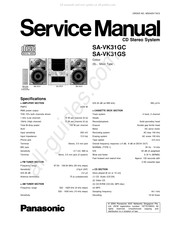
Panasonic SA-VK31 Service Manual (116 pages)
Brand: Panasonic
|
Category: Stereo System
|
Size: 18.38 MB
Table of Contents
Advertisement
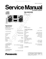
Panasonic SA-VK31 Service Manual (115 pages)
Brand: Panasonic
|
Category: Stereo System
|
Size: 20.77 MB
Table of Contents
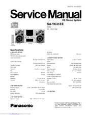
Panasonic SA-VK31 Service Manual (116 pages)
Brand: Panasonic
|
Category: Stereo System
|
Size: 18 MB
Table of Contents
Advertisement
Panasonic SA-VK31 Service Manual (115 pages)
Brand: Panasonic
|
Category: Stereo System
|
Size: 20.38 MB
Table of Contents
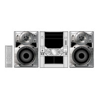
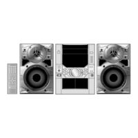
PANASONIC SA-VK31 Operating Instructions Manual (40 pages)
CD Stereo System
Brand: PANASONIC
|
Category: Stereo System
|
Size: 10.93 MB