Sign In
Upload
Manuals
Brands
Panasonic Manuals
Stereo System
SA-PM53E
Panasonic SA-PM53E Manuals
Manuals and User Guides for Panasonic SA-PM53E. We have
2
Panasonic SA-PM53E manuals available for free PDF download: Service Manual
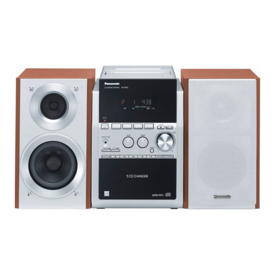
Panasonic SA-PM53E Service Manual (209 pages)
Brand:
Panasonic
| Category:
Stereo System
| Size: 8.49 MB
Table of Contents
Safety Precautions
3
General Guidelines
3
Before Repair and Adjustment
6
Protection Circuitry
6
Prevention of Electrostatic Discharge (Esd) to Electrostatically Sensitive (Es) Devices
6
Precaution of Laser Diode
7
Handling Precautions for Traverse Deck
9
Handling the Lead-Free Solder
11
About Lead Free Solder (Pbf)
11
Error Code Table
28
Assembling and Disassembling
32
Disassembly Flow Chart
33
Main Parts Location Diagram
33
Disassembly of Top Cabinet
35
Disassembly of Front Panel
37
Disassembly of Panel P.C.B
38
Disassembly of Rear Cabinet
39
Disassembly of Main P.C.B
40
Disassembly of Transformer P.C.B
41
Disassembly of Tuner Pack
42
Disassembly of Power P.C.B
43
Disassembly of CR16 Mechanism
43
Replacement of CD Lid
45
Replacement of Cassette Lid
47
Replacement of Optical Pickup Unit (CD Mechanism)
56
Replacement of a Traverse Gear a and a Traverse Gear B
60
Cr16 Mechanism Assembly Procedure
77
Disassembly of Traverse Mechanism
104
Handling of Cassette Tape Jam
106
Service Positions
107
Checking and Repairing of Transformer P.C.B
108
Checking and Repairing of Main P.C.B
109
Checking and Repairing of Panel P.C.B
110
Checking and Repairing of Power P.C.B
112
Procedure for Checking Operation of Individual Parts of Deck Mechanism Unit
113
Measurement and Adjustments
115
Voltage Measurement & Waveform Chart
119
Voltage Measurement
120
Waveform Chart
120
Schematic Diagram
123
Printed Circuit Board Diagrams
123
Troubleshooting Flowchart (CD Section Circuit)
131
Exploded Views
132
Replacement Parts List
134
Advertisement
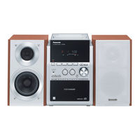
Panasonic SA-PM53E Service Manual (121 pages)
CD Stereo System
Brand:
Panasonic
| Category:
Stereo System
| Size: 21.51 MB
Table of Contents
Laser Power CLASS
1
Table of Contents
2
1 Safety Precautions
4
General Guidelines
4
Caution for AC Cord
5
Before Repair and Adjustment
6
Protection Circuitry
6
2 Prevention of Electro Static Discharge (ESD) to Electrostatically Sensitive (ES) Devices
7
3 Precaution of Laser Diode
8
4 Handling Precautions for Traverse Deck
9
5 Handling the Lead-Free Solder
10
About Lead Free Solder (Pbf)
10
6 Accessories
11
7 Operating Instructions Procedures
12
Main Unit & Remote Control Operation
12
Disc Information
13
8 Self-Diagnosis & Special Mode Setting
14
Special Mode Table
14
Error Code Table
23
9 Assembling and Disassembling
26
Caution
26
Disassembly Flow Chart
27
Main Parts Location Diagram
28
Disassembly of Side Panel L & R
29
Disassembly of Top Cabinet
29
Disassembly of Deck P.C.B. and Tape Eject
29
Disassembly of Front Panel
30
Disassembly of Panel P.C.B
30
Disassembly of Rear Cabinet
31
Disassembly of Main P.C.B
31
Disassembly of Transformer
32
Disassembly of Tuner Pack
32
Disassembly of Power P.C.B
33
Disassembly of CR16 Mechanism
33
Replacement of CD Lid
34
Replacement of Cassette Lid
35
Replacement of the Power IC
36
Procedure for Replacing Pinch Roller and Head Block (Deck Mechanism Unit)
37
Procedure for Replacing Motor, Capstan Belt A, Capstan Belt B, and Winding Belt (Deck Mechanism Unit)
37
Procedure for Replacing Parts on Deck Mechanism PCB
39
Disassembly of CR16 Mechanism
39
Replacement of Optical Pickup Unit (CD Mechanism)
40
Replacement of a Traverse Gear a and a Traverse Gear B
42
Procedure for Removing CD Loading Mechanism
43
CR16 Mechanism Disassembly Procedure
43
Cr16 Mechanism Assembly Procedure
49
Disassembly of Traverse Mechanism
62
Handling of Cassette Tape Jam
63
10 Service Positions
64
Checking and Repairing of Deck, Deck Mechanism and Tape Eject
64
Checking and Repairing of Transformer P.C.B
65
Checking and Repairing of Main P.C.B
66
Checking and Repairing of Panel
67
Checking and Repairing of CD Servo and CD Loading
68
Checking and Repairing of Power P.C.B
69
11 Procedure for Checking Operation of Individual Parts of Deck Mechanism Unit
70
Operation Check with Cassette Tape
70
Operation Check Without Cassette Tape
70
12 Measurement and Adjustments
72
Cassette Deck Section
72
13 Voltage Measurement & Waveform Chart
74
Voltage Measurement
74
Waveform Chart
77
14 Wiring Connection Diagram
79
15 Block Diagram
81
16 Notes of Schematic Diagram
85
17 Schematic Diagram
87
CD Servo Circuit
87
Main Circuit
88
Panel Circuit
90
DECK CIRCUIT, DECK MECHANISM CIRCUIT and TAPE EJECT CIRCUIT
91
Power Circuit
92
Transformer Circuit
93
CD Loading Circuit
94
18 Printed Circuit Board Diagrams
95
CD Servo P.C.b
95
Main P.C.b
96
Panel P.C.b
97
DECK P.C.B, DECK MECHANISM P.C.B and TAPE EJECT P.C.B
98
Power P.C.b
99
Transformer P.C.b
100
CD Loading P.C.b
101
19 Illustration of IC 痴, Transistors and Diodes
103
20 Terminal Function of ICエS
104
Ic7001 (Mn6627954Ma) IC Servo Processor/Digital Signal Processor/Digital Filter D/A Converter
104
IC7002 (BA5948FPE2) IC 4CH Drive
105
Ic401 (C2Cbyy000164) IC Micro Processor
105
21 Troubleshooting Flowchart (CD Section Circuit)
107
22 Exploded Views
109
Cabinet Parts Location
109
CD Loading Mechanism Parts Location
110
Deck Mechanism (RAA4402-1S) & Traverse Parts Location
111
Packaging
112
23 Replacement Parts List
113
Advertisement
Related Products
Panasonic SAPM53 - MINI HES W/CD PLAYER
Panasonic SAPM533 - MINI HES W/CD PLAYER
Panasonic SA-PM50D
Panasonic SA-PM53EB
Panasonic SA-PM53EG
Panasonic SA-PM500
Panasonic SA-PM53-MULTI
Panasonic SA-PM4E
Panasonic SA-PM29P
Panasonic SA-PM37MD
Panasonic Categories
Camcorder
Air Conditioner
TV
Digital Camera
Cordless Telephone
More Panasonic Manuals
Login
Sign In
OR
Sign in with Facebook
Sign in with Google
Upload manual
Upload from disk
Upload from URL