Sign In
Upload
Manuals
Brands
Oval Manuals
Measuring Instruments
ALTI mass CA015
Oval ALTI mass CA015 Coriolis Flowmeter Manuals
Manuals and User Guides for Oval ALTI mass CA015 Coriolis Flowmeter. We have
1
Oval ALTI mass CA015 Coriolis Flowmeter manual available for free PDF download: Instructions Manual
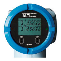
Oval ALTI mass CA015 Instructions Manual (162 pages)
Brand:
Oval
| Category:
Measuring Instruments
| Size: 10.17 MB
Table of Contents
Table of Contents
2
1 Before You Begin
5
Confirming the Tag Information
5
Transportation Guidelines
5
Storage Guidelines
5
Precautions for Operating Conditions
6
Precautions for Installation Location
6
Precautions for Power-On
6
Returning Equipment
6
2 General and Features
7
General Description
7
Features
7
3 Specifications and Performance
7
Sensor Unit General Specifications
7
Type U Sensor Unit General Specifications
7
Type S Sensor Unit General Specifications
11
Type B Sensor Unit General Specifications
11
Transmitter General Specifications
12
Max. Operating Temperature of PED Specification
12
General Performance
13
Type U General Performance
13
Type S General Performance
16
Type B General Performance
16
Display
17
4 Pressure Losses
17
Type U Pressure Losses
17
Type S Pressure Losses
19
Type B Pressure Losses
20
5 Part Names and Outline Dimensions
21
Type U
21
CA00A, CA001 and CA003 (Separately Mounted Models)
21
CA006 Thru CA080 (Integrally Mounted Models)
22
CA100 Thru CA250 (Integrally Mounted Models)
24
CA006 Thru CA080 (Separately Mounted Models)
25
CA100 Thru CA250 (Separately Mounted Models)
27
High Temperature Service Models (CA025 to CA150)
28
Low Temperature Explosionproof Service Models (CA025 to CA080)
29
Low Temperature Explosionproof Service Models (CA100 to CA250)
30
Ferrule Fitting Type
31
Type S
33
Stainless Steel Tube Type (Integrally and Separately Mounted Models)
33
Low Temperature Explosionproof Service Models)
34
Titanium Tube Type (Integrally and Separately Mounted Models)
34
Ferrule Fitting Type (Integrally and Separately Mounted Models)
35
Type B
36
Integrally Mounted Models
36
Separately Mounted Models
37
Separately Mounted Transmitter
38
6 Installation
38
Physical Orientation
39
Type U Physical Orientation
39
Type S Physical Orientation
40
Type B Physical Orientation
41
Installation Location
42
Installation Guidelines
43
Standard Piping Conditions
43
Influence of Vibration and Pulsation
44
Prevention of Cavitation
44
Prevention of Excessive Flows
44
Prevention of Gas Mixed Flows
44
Keeping the Sensor Filled with Process Liquid
44
Bypass Loop
45
Installation Guidelines
46
Flange Type
46
Sanitary Fitting Type
47
Screw-In Type
47
Installing Proper Pipe Supports
48
Type U Pipe Supports
48
Type S Pipe Supports
49
Type B Pipe Supports
49
Heat and Cold Retention Procedures
50
Type U
50
Type S
51
Type B
51
A Boss for Pressure Relief Device - Its Use
52
Separately Mounted Transmitter Installation
52
How to Change Transmitter Orientation
53
How to Change Transmitter Display Orientation
54
7 Wiring Instructions
57
Wiring Connections
57
Power and Output Signal Connections (both Integrally and Separately Mounted Models)
57
Connections between Separately Mounted Sensor Unit and Transmitter
58
Power Supply Lines and Ground Terminal
58
Analog Output Wiring
58
Pulse Output Wiring
59
Status Output Wiring
59
Status Input Wiring
60
Communication Line Wiring (Option)
60
Recommended Cables Condition
60
Terminal Identification of Separately Mounted Transmitter
61
Wiring Diagram
62
Transmitter Power and Output Signal Wiring
62
Separately Mounted Sensor Unit and Transmitter Wiring
63
How to Change Cable Entry Orientation of Terminal Box (Separately Mounted Type)
64
8 Operation
66
Flushing the Piping Assembly
66
Confirming the Sensor Unit for Correct Installation
66
Leak Check
66
Supplying the Power
66
Measurement Line Startup
66
Warm-Up
66
Zeroing Procedure
66
Readying for Operation
66
9 Description of Incorporated Functions
67
Display
67
Description of Display
67
Switch Operation
68
Viewing the Variables
69
Viewing the Parameters and Description
71
Viewing the Setup Menu
71
Transition Chart of View (1)
72
Transition Chart of View (2)
74
Transition Chart of View (3)
76
Transition Chart of View (4)
78
Transition Chart of View (5)
80
Transition Chart of View (6)
82
Parameter Value Entry
84
Parameter Selection
85
Password Function
86
Password Function Setup
86
Self-Diagnostic Capabilities
87
Probe Check
87
Drive Coil Check
88
Transmitter Check
89
Pipeline Vibration Check (at Zero Flow)
90
Pipeline Oscillation Check (at Normal Flow)
91
Simulated Signal Input/Output Capabilities
92
Analog Output
92
Pulse Output
93
Status Output
94
Status Input
95
Zeroing Function
96
Through LCD Display Switches
96
Through Status Input Signal
97
Through Link Top Communication
97
Analog Trim Function
98
Reset Function
99
View Variables Screen Setup
100
Pulse Output Function
101
Pulse Output 1
101
Pulse Output 2
101
Bidirectional Pulse Output
102
Double Pulse Input
103
Analog Output Function
104
Status Output Function
105
Status Output (Error Status)
105
Bidirectional Flow Direction Output (Bi Direction)
105
H/L Alarm Output (H/L Alarm)
106
Drive Output Alarm (Used for Maintenance Purpose)
106
No Assignment (no Function)
106
Status Input Function
107
Pulse/Analog Output Fixed at 0% (0% Sig Lock)
107
Zero Adjustment (Auto Zero)
107
Totalizer 1 and Totalizer 2 Reset (Reset Total 1 and 2)
107
Totalizer 1 Reset (Reset Total 1)
108
Totalizer 2 Reset (Reset Total 2)
108
High/Low Alarms Function
109
Gas Mixed Flow Alarm
111
Setup Units List
113
10 Maintenance
114
Error Messages
114
A List of Status Messages
115
Replacement Parts
116
Explosionproof Specification
117
TIIS Explosionproof
117
ATEX/ Iecex Explosionproof
118
Kcs Explosionproof
119
CSA Explosionproof
120
EAC Explosionproof
122
NEPSI Explosionproof
123
ITRI Explosionproof
124
Detector Model Specification Table 1(TIIS Explosionproof
125
Detector Model Specification Table
126
ATEX, Iecex, Kcs, CSA, EAC, NEPSI, ITRI Explosionproof
126
Electric Wire Connection Part of Integral Type / Separate Type Converters
127
Electric Wire Connection Ports of Separate Type Converter/ Separate Type Detector
132
Ambient Temperature (Type U)
134
Precautions on the Explosionproof Specification
135
About the Explosionproof
135
About Cable Gland
135
About Blanking Plug
136
Insulation Performance
136
Earthing Terminal
136
About Dedicated Cable (for Only Separate Type)
136
Maintenance and Checking
137
11 Ex-Information
138
Nameplates
138
Regarding FISCO System of FOUNDATION Fieldbus and PROFIBUS
141
12 About Maritime Certification
143
13 Regarding Ehedg Certification
144
14 Product Code Explanation
145
Type U
145
Type S
148
Stainless Steel Tube Type
148
Titanium Tube Type
150
Type B
152
15 Product Code Explanation of the Old Product Code
154
Type U Product Codes
154
CA00A to CA080
154
CA100 to CA250
155
Type S Product Codes
156
Type B Product Codes
157
Shipping Parameters
158
Safety Statement of Returned Goods
160
Repair Request Sheet
161
Advertisement
Advertisement
Related Products
Oval ALTImass CA004
Oval ALTI mass CA00A
Oval ALTI mass CA001
Oval ALTI mass CA003
Oval ALTI mass CA006
Oval ALTI mass CA010
Oval ALTI mass CA025
Oval ALTI mass CA040
Oval ALTI mass CA050
Oval ALTI mass CA080
Oval Categories
Measuring Instruments
Desktop
Cell Phone
Conference System
Industrial Equipment
More Oval Manuals
Login
Sign In
OR
Sign in with Facebook
Sign in with Google
Upload manual
Upload from disk
Upload from URL