Sign In
Upload
Manuals
Brands
OTARI Manuals
Recording Equipment
MTR-10II Series
OTARI MTR-10II Series Manuals
Manuals and User Guides for OTARI MTR-10II Series. We have
2
OTARI MTR-10II Series manuals available for free PDF download: Operation And Maintenance Manual, Interface Manual
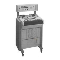
OTARI MTR-10II Series Operation And Maintenance Manual (291 pages)
Brand:
OTARI
| Category:
Recording Equipment
| Size: 147.19 MB
Table of Contents
Safety Instructions
2
Table of Contents
4
Important Notice
9
Newly Added Operation with PB-4GEA Master CPU PCB Assembly
12
Brake Stopper Kit Parts List
14
Brake Stopper Kit Installation
14
Brake Stopper Kit Adjustment
15
Using this Manual
17
Model List
17
Section 1: Introduction
17
Product Overview
19
Otari Mtr-10 and Mtr-12 Series Master Production Recorders
19
Product View
22
Reference Photographs
22
Control Panel View
25
Tape Transport Controls View
26
2-Channel Rear Panel Connectors
26
Auto Locator View
27
Remote Control Box View
27
Inspection
29
Section 2: Installation
29
Transport Panel Release Lever
31
Function Selection on Master CPU PCB Assembly
37
Connections
39
Line Input and Line Output
39
XLR Cable Wiring for Audio Connections
39
Interconnect Cable for Optional Auto Locator
40
Audio, Power and External Control/Sync Connections
40
Interconnect Cable for Optional Remote Control Box
41
Remote Mode Switching for Noise Reduction Equipment
41
Parellel I/O Connector
41
Noise Reduction Connector Pin Assignment
41
AC Power Connection
42
Controls and Indicators: Quick Reference Guide
44
Section 3: Functional Checkout and Basic Operation
44
General
44
Transport Features
45
Audio/Monitor Control Panel, Card Cage and Power Supply Features
46
Power Supply Indicators
47
Speed Switch
47
Forward Button, Rewind Button
47
Stop/Load Button
47
Play Button
48
Record Button
48
Edit/Unload Button
48
Speed Mode Switch
49
Pitch Control
50
Cue Button
50
Cue Lever
50
Tape Time Display/Tape Timer Reset Button
50
Search Zero Button
51
Tape Speed Display
51
"Ips - %" Button
51
End of Tape (Safety) Switch
51
Input Level Controls
52
Output Level Controls
52
SRL Buttons and Indicators
52
VU Meters
52
Record Mode Switches (Ready/Safe) and Record Mode Indicators
53
Test OSC Switch and EXT OSC Jack
53
Monitor Selector Buttons
54
Phones Jack
54
LF COMP Switches
54
Master Bias Switch
54
REF FLUX Switch and REF FLUX Indicators
55
Capstan Lock Indicator
55
Test Switch and CPU Condition (Run) Indicator
55
Functional Checkout
56
Reel Installation
56
Reel Clamp Installation for Small and Large Reels
57
Checking Tension Compensation for Tape Width
58
Powering up
58
Loading Tape on the Transport
59
Tape Threading Diagram
59
The Tape Speed and Record/Play Equalization Selectors
60
Normal Play Mode
61
Reverse Play Mode
61
Fast Winding Modes
61
Spooling Mode
62
Shuttle Cue Mode
62
Fast Cue Mode
62
Edit/Unload
63
Speed Mode Selection
63
Search to Zero
64
Remote Control Box (Remote Box) Functional Checkout
65
The Auto Locator
65
Audio/Monitor Control Function (Including Record) Checkout
65
Record Mode
65
Input Mode
66
Sel-Rep Mode
66
Individual Channel Output Selection (Audio Monitor)
66
Input and Output Level Controls
67
Repro (Play) Mode
67
Section 4: Audio Alignment
70
General Description
70
Front Panel Controls on the Audio
71
Demagnetizing the Heads and Tape Guidance Path
73
Cleaning the Tape Path
74
Audio Circuit Board Preliminary Alignment (Occasional)
74
Important Note Regarding Level Measurements
76
Repro (and SEL-REP) Alignment
77
Repro and Record Head Azimuth Adjustment Screws
78
Record Aligmnent
79
Bias Adjustment
79
Removal of the Head Assembly Rear Cover
80
Head Assembly Circuit Board Bias Test Points
80
Record Level Adjustment
82
Record Equalization Adjustment
82
Phase Compensation
83
Time Code Module Alignment
84
Low Frequency Compensation (LF Comp)
84
Head Alignment
84
Azimuth Adjustment and Head Height Adjustment
84
Reproduct Alignment
85
Output Level Alignment
85
Record Alignment
85
Reproduce Level Adjustment
85
Bias Adjustment
85
Input Level Adjustment
86
LED Threshold Adjustment
86
Fine Adjustment of Delay Time
87
Head Geometry
90
Access to the Undeside of the Transport Deck Plate
90
Section 5: Transport Alignment
90
General Description
90
Capstan Pinch Roller Solenoid Travel (and Pressure)
91
Measuring Pinch Roller Tension
92
Brake Torque
93
Brake Tension Measurement Using a Spring Scale
93
Spring Retaining Bracket for Brake Tension Adjustment
94
Reel Turntable Height
95
Tape Lifters
95
Supply and Takeup Reel Tension and Speed Adjustments
96
Takeup Reel Tension
97
Zero Search Slow Speed Crawl
98
Past Wind Speed
98
Reel Control Board Internal Adjustments and Test Points
99
Tachometer Phase
100
Correct Tachometer Output in Play Mode
100
Test Points on Reel Control PCB for Tach Phase Check
101
Reverse Play Speed and Reel Motor Drive Amplifier (MDA) Gain
102
Counter Tachometer Board on Underside of Transport
102
Capstan Control Board (D)
104
Capstan Gain
104
Capstan Damping
104
Capstan Control Board Check Points and Adjustments
105
External Sync Input Calibration
106
Cue Lever Offset and Maximum Speed
106
Operation
110
Recording Initial Tracks
110
General
110
Playback of Initial Tracks
111
Rel-Rep Recording (Overdubbing)
112
Sel-Rep Recording (Punch-Ins)
113
Rehearsal of Overdubs on Punch-Ins
114
Hand Spooling
115
Dump Edit
115
Spooling Mode
115
Use of Variable Speed Mode
117
Use of an External Speed Reference
117
Using SMPTE Synchronization And/Or Location Control
118
Connecting a Synchronizer to the Unit
118
General
118
Interface of the Otari Mtr-I0 to the Btx Shadow
119
Adding a Diode to Transport Control Board for Mute/Unmute Operation
122
Interface of the Unit to Audio Kinetics "Q-Lock" SMTE Synchronizers
123
Interface of the Otari Mtr-I0 to Audio
123
Interface of the Unit to Adams-Smith 2600 SMPTE Synchronizers
124
Interface of the Otari Mtr-10 to Adams-Smith 2600
124
Parallel I/O Connector Assignment
127
Time Code Unit Description
129
Ready/Safe Switch
129
Monitor Mode Select Switch
129
Specification for Time Code Version
131
Auto Locator Installation
133
Section 7: Auto Locator
133
General
133
Tape Time
134
Auto Locator Controls and Indicators
135
Locate Time
136
Keyboard Numerals
136
Shift Left and Shift Right
136
Conventional Store/Recall/Search Vs. Direct Store/Search
137
Conventional Memory Store
137
Load
137
Direct Memory Store
138
Clearing (Zeroing) a Memory
138
Search Zero
139
Conventional Memory Recall and Search
139
Direct Memory Search
139
Shuttle
140
Auto Rewind
141
Transport Controls
141
Examples of Auto Locator Operation
141
Clearing a Direct Store Memory
145
"Illegal" Commands
145
Overbridge Conversion Kit/Standard Console Conversion Kit
148
Full Track Conversion Head Assembly
148
DIN Track Conversion Head Assembly
148
Section 8: Field Conversions
148
Parts Kit for Modification of 1/2" Model into 1/4" Model
149
MODIFICATION for LOW SPEED OPERATION (3.75, 7.5, 15 Ips)
149
Audio Boards
150
Component Changes on Audio Boards for Low Speed Operation
151
Unit with Overbridge Installed View
152
Parts Kit for Center Track Conversion
154
Record/Reproduct Electronics - General Information
156
Repro Head and Electronics
156
Section 9: Circuit Description
156
Audio Output Stage
157
Record Electronics
158
Bias/Erase Circuitry and Timing
158
Master CPU: Board "B"
159
Transport Control: Board "A"
160
Reel Control: Board "C"
160
Capstan Control: Board "D"
161
Removing and Reinserting Printed Circuit Boards
165
Section 10: Maintenance
165
General
165
Reel Motor Replacement
166
Brake Pad Replacement
167
Meter or Meter Lamp Replacement
167
Capstan Pinch Roller Removal and Replacement
168
Takeup Roller Guide Removal and Replacement
168
Takeup Roller Guide Disassembly
168
Impedance Roller (Supply Reel Roller) Removal and Replacement
169
Tachometer Roller Removal and Replacement
169
Cleaning and Lubrication
170
Reel Motor Drive Circuit Boards Removal and Replacement
170
Safety Shut-Off Switch Assembly Removal and Replacement
171
Swing Arm Assembly Removal and Replacement
171
Capstan Motor Removal and Replacement
172
Tape Transport Data
174
Section 11: Specifications
174
Electronics
175
Physical Data
176
Accessories
177
Parts Lists and PCB Assemblies
180
Parts Lists and Exploded View Drawings
199
Electrical Diagrams
250
Advertisement
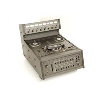
OTARI MTR-10II Series Interface Manual (22 pages)
SYNCHRONIZER INTERFACE INFORMATION
Brand:
OTARI
| Category:
Recording Equipment
| Size: 0.79 MB
Advertisement
Related Products
OTARI MTR-12II Series
OTARI MTR-10I Series
OTARI MTR-12I Series
OTARI MTR-10 Series
OTARI MTR-12 Series
OTARI MTR-90III
OTARI MTR Series
OTARI MTR-90II Series
OTARI MTR-90I Series
OTARI MTR-20 Q
OTARI Categories
Recording Equipment
Voice Recorder
Measuring Instruments
VCR
Tape Deck
More OTARI Manuals
Login
Sign In
OR
Sign in with Facebook
Sign in with Google
Upload manual
Upload from disk
Upload from URL