Sign In
Upload
Manuals
Brands
Oshkosh Corporation Manuals
Boom Lifts
JLG E400AJP
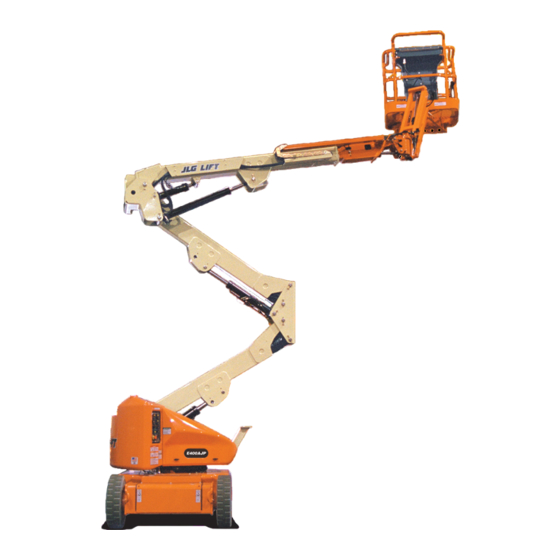
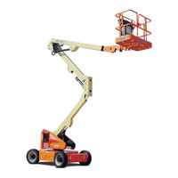
Oshkosh Corporation JLG E400AJP Boom Lift Manuals
Manuals and User Guides for Oshkosh Corporation JLG E400AJP Boom Lift. We have
6
Oshkosh Corporation JLG E400AJP Boom Lift manuals available for free PDF download: Service And Maintenance Manual, Operation And Safety Manual
Oshkosh Corporation JLG E400AJP Service And Maintenance Manual (492 pages)
Brand:
Oshkosh Corporation
| Category:
Boom Lifts
| Size: 58.96 MB
Table of Contents
General
3
Bhydraulic System Safety
3
Maintenance
3
Table of Contents
5
Specifications
20
Operating Specifications
20
Capacities
20
Tires
20
Dimensional Data
21
Lubrication Specifications
21
Hydraulic Oil
21
Critical Stability Weights
22
Torque Specifications
22
Major Component Weights
23
Serial Number Locations
23
Maintenance and Lubrication
25
General
34
Machine Preparation, Inspection, and Maintenance
34
Preparation, Inspection, and Maintenance
34
Pre-Start Inspection
34
Pre-Delivery Inspection and Frequent Inspection
34
Annual Machine Inspection
34
Preventative Maintenance
34
Service and Guidelines
35
General
35
Safety and Workmanship
35
Cleanliness
35
Components Removal and Installation
35
Component Disassembly and Reassembly
36
Pressure-Fit Parts
36
Bearings
36
Gaskets
36
Bolt Usage and Torque Application
36
Hydraulic Lines and Electrical Wiring
36
Hydraulic System
36
Lubrication
37
Battery
37
Lubrication and Servicing
37
Lubrication and Information
37
Hydraulic System
37
Hydraulic Oil
37
Changing Hydraulic Oil
37
Lubrication Specifications
37
Cylinder Drift
38
Theory
38
Cylinder Leakage Test
38
Cylinder Thermal Drift
38
Pins and Composite Bearing Repair Guidelines
39
Welding on JLG Equipment
39
Do the Following When Welding on JLG Equipment
39
Do NOT Do the Following When Welding on JLG Equipment
39
Chassis & Turntable
45
Tires & Wheels
45
Tire Inflation
45
Tire Damage
45
Tire Replacement
45
Wheel Replacement
45
Wheel Installation
45
Spindle
46
Setting Wheel Bearing End Play
46
Specifications
46
Checking
46
Greasing Requirements
46
Tilt Module
49
Speed Sensor
51
Drive Hub
57
Roll and Leak Testing
57
Tightening and Torquing Bolts
57
Main Disassembly
58
Output Carrier Disassembly
60
Input Carrier Disassembly
62
Hub-Spindle Disassembly
63
Cover Disassembly
64
Input Carrier Assembly
65
Output Planet Gear Assembly
65
Output Carrier Assembly
66
Hub-Spindle Assembly
66
Cover Assembly
67
Main Assembly
67
Drive Motor
70
Removal
70
Disassembly
70
Inspection
70
Assembly
71
Installation
71
Swing Bearing
73
Turntable Bearing Mounting Bolt Condition Check
73
Wear Tolerance
74
Replacement of Swing Bearing
75
Swing Bearing Torque Value
79
Checking Worm Gear End Play
79
Adjusting End Play
79
Swing Motor
81
Preparation before Disassembly
84
Disassembly and Inspection
84
Assembly
91
One Piece Stator Construction
97
Two Piece Stator Construction
98
Final Checks
98
Battery Maintenance and Charging
99
Battery Maintenance, Quarterly
99
Optional on Board Generator
99
Battery Charging (on Board Charger)
99
Battery Charger
101
Operating Instructions
101
Maintenance Instructions
102
Battery Charger Fault Codes
102
Excessive Battery Watering Requirements or Strong Sulphur (Rotten Egg) Smell
106
Checking/Changing the Battery Charger Algorithm
106
Generator
107
Engine
107
Alternator
107
Dynamo and Dynamo Voltage Regulator
107
Dynamo Output Fuse
107
Control Fuse
107
Start Battery
109
Engine Starter
109
Start Control Relay
109
Fuel Control Relay
110
Glow Plug Control Relay
110
Glow Plug
110
Fuel Pump
111
Fuel Solenoid
111
Engine Low Oil Pressure Switch
111
Engine Oil Temperature Sensor
111
Alternator Output Current Sensor
112
Engine Speed Sensor
112
RBS Engine/Generator Controller
112
Warnings and Safety Precautions
113
System Controls
113
System Status and Performance Monitoring
113
System Settings
113
RBS Start
114
RBS Shutdown
114
RBS Alarms and Flash Codes
115
Resetting the RBS Controller
115
Maintenance Schedule
115
Troubleshooting
116
APU Engine Start Battery Boosting
117
Supplementary Fuse for APU
118
Tools and Material
118
Procedure
118
Boom & Platform
121
Platform
121
Support Removal
121
Support Installation
122
Rotator and Slave Cylinder Removal
124
Removal
124
Installation
124
Main Boom Powertrack
125
Removal
125
Installation
125
Boom Maintenance
126
Removal
126
Disassembly
127
Inspection
127
Assembly
127
Installation
128
Wear Pads
129
Boom Limit Switches
129
Boom Cleanliness Guidelines
129
Articulating Jib Boom
132
Removal
132
Disassembly
132
Inspection
132
Assembly
132
Boom Synchronizing Procedure
133
Footswitch Adjustment
133
Rotary Actuator
134
Theory of Operation
134
Tools Required for Assembly/Disassembly
134
Disassembly
137
Inspection
140
Assembly
141
Installing Counterbalance Valve
145
Greasing Thrust Washers
146
Testing the Actuator
146
Installation and Bleeding
147
Troubleshooting
148
Powertrack Maintenance
149
Removing a Link
149
Installing a New Link
152
Replacing Fixed End Brackets
157
Replacing Moving End Brackets
159
Skyguard
161
Operation
161
Function Test
161
Diagnostics & Troubleshooting
162
Basic Hydraulic Information & Schematics
164
Lubricating O-Rings in the Hydraulic System
164
Cup and Brush
164
Dip Method
165
Spray Method
165
Brush-On Method
165
Hydraulic Connection Assembly and Torque Specification
166
Tapered Thread Types
166
Straight Thread Types, Tube and Hose Connections
166
Straight Thread Types, Port Connections
167
Flange Connection Types
167
Tightening Methods
167
Assembly and Torque Specifications
168
Assembly Instructions for American Standard Pipe Thread Tapered (NPTF) Connections
169
Assembly Instructions for British Standard Pipe Thread Tapered (BSPT) Connections
170
Assembly Instructions for 37° (JIC) Flare Fittings
171
Assembly Instructions for 45° SAE Flare Fittings
175
Assembly Instructions for O-Ring Face Seal (ORFS) Fittings
177
Assembly Instructions for DIN 24° Flare Bite Type Fittings (MBTL and MBTS)
179
Assembly Instructions for Bulkhead (BH) Fittings
181
Assembly Instructions for Adjustable Port End Metric (MFF) Fittings
193
Assembly Instructions for Metric ISO 6149 (MPP) Port Assembly Stud Ends
201
Assembly Instructions for Adjustable Port End (BSPP) Fittings
203
Assembly Instructions for Flange Connections: (FL61 and FL62)
211
Double Wrench Method
214
FFWR and TFFT Methods
215
Adjustable Stud End Assembly
215
O-Ring Installation (Replacement)
216
Hydraulic Cylinders
217
Slave Cylinder (E400AN Only)
217
Slave Cylinder (E400AJP/M400AJP/E400AJPN/M400AJPN Only)
222
Jib Lift Cylinder
227
Lower Lift Cylinder (E400AN Only)
232
Lower Lift Cylinder (E400AJP/M400AJP/E400AJPN/M400AJPN Only)
239
MID Lift Cylinder(E400AN Only)
246
Advertisement
Oshkosh Corporation JLG E400AJP Service And Maintenance Manual (261 pages)
Brand:
Oshkosh Corporation
| Category:
Boom Lifts
| Size: 20.15 MB
Table of Contents
Bhydraulic System Safety
3
Maintenance
3
Table of Contents
5
Section 1 - Specifications
16
Operating Specifications
16
Capacities
16
Battery Charger
16
Drive System
16
Hydraulic Pump/Electric Motor Assembly
16
Generator
16
Tires
16
Dimensional Data
17
Function Speeds
17
Machine Orientation When Doing Function Tests
18
Torque Specifications
18
Cylinder Specifications
19
Major Component Weights
19
Critical Stability Weights
20
Pressure Settings
20
Serial Number Locations
21
Lubrication
21
Lubrication Specifications
21
Operator Maintenance & Lubrication
23
Section 2 - General
34
Machine Preparation, Inspection, and Maintenance
34
General
34
Preparation, Inspection, and Maintenance
34
Pre-Start Inspection
34
Pre-Delivery Inspection and Frequent Inspection
34
Annual Machine Inspection
34
Preventive Maintenance
34
Service and Guidelines
35
General
35
Safety and Workmanship
35
Cleanliness
35
Components Removal and Installation
35
Component Disassembly and Reassembly
36
Pressure-Fit Parts
36
Bearings
36
Gaskets
36
Bolt Usage and Torque Application
36
Hydraulic Lines and Electrical Wiring
36
Hydraulic System
36
Lubrication
36
Battery
36
Lubrication and Servicing
36
Hydraulic Oil
37
Changing Hydraulic Oil
37
Lubrication Specifications
37
Cylinder Drift Test
37
Platform Drift
37
Cylinder Drift
37
Pins and Composite Bearing Repair Guidelines
38
Welding on JLG Equipment
38
Do the Following When Welding on JLG Equipment
38
Do NOT Do the Following When Welding on JLG Equipment
38
Engine Operating Temperature Specifications - Kubota
42
Section 3 - Chassis & Turntable
44
Tires & Wheels
44
Tire Inflation
44
Tire Damage
44
Tire Replacement
44
Wheel Replacement
44
Wheel Installation
44
Spindle
45
Setting Wheel Bearing End Play
45
Specifications
45
Checking
45
Greasing Requirements
45
Drive Hub (Part No. 2780236)
47
Dissembling
47
Disassembly
48
Disassembly of the First Stage Planetary Assembly (7)
48
Disassembly of Second Stage Planet Gears (1)
48
Assembly of First Stage Planetary Assembly (7)
48
Assembly of End Cover Unit (8)
48
Final Assembly
49
Initial Start-Up and after Repairs
49
Maintenance
49
Oil Change Interval-Gear Drive
49
Setting of Tapered Roller Bearings
49
Securing of the Shaft Nut
49
Drive Hub- Cutaway
49
Drive Brake - Mico
51
Disassembly
51
Assembly
51
Bleeding
51
Drive Brake
51
Speed Sensor Adjustment
54
Adjustment Procedure
54
Speed Sensor Orientation
55
Speed Sensor Installation Verification
59
Verification W/ Analyzer Procedure
59
Positrac/Tilt Module
62
Swing Motor - S/N 0300135649 to Present
64
Swing Motor - Cutaway
64
Swing Motor - Exploded View
66
Preparation before Disassembly
67
Disassembly and Inspection
67
Assembly
73
One Piece Stator Construction
80
Two Piece Stator Construction
81
Final Checks
81
Swing Bearing
82
Turntable Bearing Mounting Bolt Condition Check
82
Swing Bearing Feeler Gauge Check
82
Wear Tolerance
83
Swing Bearing Tolerance Boom Placement
83
Replacement of Swing Bearing
84
Swing Bearing Tolerance Measuring Point
84
Swing Bearing Torquing Sequence
85
Swing Bearing Torque Value
86
Checking Worm Gear End Play
86
Adjusting End Play
86
Battery Maintenance and Charging
88
Battery Maintenance, Quarterly
88
Charging Sequence of Remote LED Card
88
Remote LED Card
88
Battery Cable Connections
89
Battery Charging (on Board Charger)
90
Optional on Board Generator
90
Batteries and Battery Charger (Prior to S/N 0300059350)
90
On Board Generator
90
Battery Charger (S/N 0300059350 to Present)
92
Battery Charger ((S/N 0300059350 to Present)
92
Operating Instructions
92
Maintenance Instructions
92
Battery Charger Fault Codes
92
Excessive Battery Watering Requirements or Strong Sulphur (Rotten Egg) Smell
95
Checking/Changing the Battery Charger Algorithm
96
Generator (Prior to S/N 88539)
97
Alternator
97
Dynamo and Dynamo Voltage Regulator
97
Dynamo Output Fuse
97
Control Fuse
97
Start Battery
97
Engine Starter
97
Start Control Relay
97
Fuel Control Relay
97
Fuel Solenoid
97
To Connect the JLG Control System Analyzer to the Generator
100
Alarms and Fault Flash Codes
100
Output Current and Voltage Settings
102
Priming the Fuel Line
103
Generator (S/N 88539 to Present)
104
Engine
104
Alternator
104
Dynamo and Dynamo Voltage Regulator
104
Dynamo Output Fuse
104
Control Fuse
104
Start Battery
106
Engine Starter
106
Start Control Relay
106
Fuel Control Relay
107
Glow Plug Control Relay
107
Glow Plug
107
Fuel Pump
108
Fuel Solenoid
108
Engine Low Oil Pressure Switch
108
Engine Oil Temperature Sensor
108
Alternator Output Current Sensor
109
Engine Speed Sensor
109
RBS Engine/Generator Controller
109
Warnings and Safety Precautions
110
System Controls
110
System Status and Performance Monitoring
110
System Settings
110
RBS Start
111
RBS Shutdown
111
RBS Alarms and Flash Codes
112
Resetting the RBS Controller
112
Maintenance Schedule
112
Troubleshooting
113
APU Engine Start Battery Boosting
114
Supplementary Fuse for Apu
115
Tools and Material
115
Procedure
115
Section 4 - Boom & Platform
118
Boom Maintenance
118
Removal
118
Disassembly
118
Inspection
119
Assembly
119
Installation
120
Upper (Main) Boom Lift Cylinder
121
Removal
121
Installation
121
MID Boom Lift Cylinder
121
MID Boom Lift Cylinder Removal
121
Installation
122
Lower Boom Lift Cylinder
122
Removal
122
Lower Boom Lift Cylinder Removal
122
Upper Boom Telescope Cylinder
123
Removal
123
Installation
123
MID and Lower Lift Cylinder Bleeding Procedure
124
Wear Pads
124
Boom Synchronizing Procedure
125
Articulating Jib Boom
125
Removal
125
Disassembly
125
Inspection
125
Assembly
127
Footswitch Adjustment
127
Boom Limit Switches
127
Helac Rotary Actuator
129
Theory of Operation
129
Tools Required for Assembly/Disassembly
132
Disassembly
132
Inspection
136
Assembly
136
Installing Counterbalance Valve
140
Oshkosh Corporation JLG E400AJP Service And Maintenance Manual (258 pages)
Brand:
Oshkosh Corporation
| Category:
Boom Lifts
| Size: 16.59 MB
Table of Contents
Bhydraulic System Safety
3
Maintenance
3
Table of Contents
5
Section 1 - Specifications
15
Operating Specifications
15
Capacities
15
Battery Charger
15
Drive System
15
Hydraulic Pump/Electric Motor Assembly
15
Generator
15
Tires
15
Dimensional Data
16
Function Speeds
16
Machine Orientation When Doing Function Tests
17
Torque Specifications
17
Cylinder Specifications
18
Major Component Weights
18
Critical Stability Weights
19
Pressure Settings
19
Serial Number Locations
20
Lubrication
20
Lubrication Specifications
20
Operator Maintenance & Lubrication
22
Section 2 - General
33
Machine Preparation, Inspection, and Maintenance
33
General
33
Preparation, Inspection, and Maintenance
33
Pre-Start Inspection
33
Pre-Delivery Inspection and Frequent Inspection
33
Annual Machine Inspection
33
Preventive Maintenance
33
Service and Guidelines
34
General
34
Safety and Workmanship
34
Cleanliness
34
Components Removal and Installation
34
Component Disassembly and Reassembly
35
Pressure-Fit Parts
35
Bearings
35
Gaskets
35
Bolt Usage and Torque Application
35
Hydraulic Lines and Electrical Wiring
35
Hydraulic System
35
Lubrication
35
Battery
35
Lubrication and Servicing
35
Hydraulic Oil
36
Changing Hydraulic Oil
36
Lubrication Specifications
36
Cylinder Drift Test
36
Platform Drift
36
Cylinder Drift
36
Pins and Composite Bearing Repair Guidelines
37
Welding on JLG Equipment
37
Do the Following When Welding on JLG Equipment
37
Do NOT Do the Following When Welding on JLG Equipment
37
Engine Operating Temperature Specifications - Kubota
41
Section 3 - Chassis & Turntable
43
Tires & Wheels
43
Tire Inflation
43
Tire Damage
43
Tire Replacement
43
Wheel Replacement
43
Wheel Installation
43
Spindle
44
Setting Wheel Bearing End Play
44
Specifications
44
Checking
44
Greasing Requirements
44
Drive Hub (Part No. 2780236)
46
Dissembling
46
Disassembly
47
Disassembly of the First Stage Planetary Assembly (7)
47
Disassembly of Second Stage Planet Gears (1)
47
Assembly of First Stage Planetary Assembly (7)
47
Assembly of End Cover Unit (8)
47
Final Assembly
48
Initial Start-Up and after Repairs
48
Maintenance
48
Oil Change Interval-Gear Drive
48
Setting of Tapered Roller Bearings
48
Securing of the Shaft Nut
48
Drive Hub- Cutaway
48
Drive Brake - Mico
50
Disassembly
50
Assembly
50
Bleeding
50
Drive Brake
50
Speed Sensor Adjustment
53
Adjustment Procedure
53
Speed Sensor Orientation
54
Speed Sensor Installation Verification
58
Verification W/ Analyzer Procedure
58
Positrac/Tilt Module
61
Swing Motor - S/N 0300135649 to Present
63
Swing Motor - Cutaway
63
Swing Motor - Exploded View
65
Preparation before Disassembly
66
Disassembly and Inspection
66
Assembly
72
One Piece Stator Construction
79
Two Piece Stator Construction
80
Final Checks
80
Swing Bearing
81
Turntable Bearing Mounting Bolt Condition Check
81
Swing Bearing Feeler Gauge Check
81
Wear Tolerance
82
Swing Bearing Tolerance Boom Placement
82
Replacement of Swing Bearing
83
Swing Bearing Tolerance Measuring Point
83
Swing Bearing Torquing Sequence
84
Swing Bearing Torque Value
85
Checking Worm Gear End Play
85
Adjusting End Play
85
Battery Maintenance and Charging
87
Battery Maintenance, Quarterly
87
Charging Sequence of Remote LED Card
87
Remote LED Card
87
Battery Cable Connections
88
Battery Charging (on Board Charger)
89
Optional on Board Generator
89
Batteries and Battery Charger (Prior to S/N 0300059350)
89
On Board Generator
89
Battery Charger (S/N 0300059350 to Present)
91
Battery Charger ((S/N 0300059350 to Present)
91
Operating Instructions
91
Maintenance Instructions
91
Battery Charger Fault Codes
91
Excessive Battery Watering Requirements or Strong Sulphur (Rotten Egg) Smell
94
Checking/Changing the Battery Charger Algorithm
95
Generator (Prior to S/N 88539)
96
Alternator
96
Dynamo and Dynamo Voltage Regulator
96
Dynamo Output Fuse
96
Control Fuse
96
Start Battery
96
Engine Starter
96
Start Control Relay
96
Fuel Control Relay
96
Fuel Solenoid
96
To Connect the JLG Control System Analyzer to the Generator
99
Alarms and Fault Flash Codes
99
Output Current and Voltage Settings
101
Priming the Fuel Line
102
Generator (S/N 88539 to Present)
103
Engine
103
Alternator
103
Dynamo and Dynamo Voltage Regulator
103
Dynamo Output Fuse
103
Control Fuse
103
Start Battery
105
Engine Starter
105
Start Control Relay
105
Fuel Control Relay
106
Glow Plug Control Relay
106
Glow Plug
106
Fuel Pump
107
Fuel Solenoid
107
Engine Low Oil Pressure Switch
107
Engine Oil Temperature Sensor
107
Alternator Output Current Sensor
108
Engine Speed Sensor
108
RBS Engine/Generator Controller
108
Warnings and Safety Precautions
109
System Controls
109
System Status and Performance Monitoring
109
System Settings
109
RBS Start
110
RBS Shutdown
110
RBS Alarms and Flash Codes
111
Resetting the RBS Controller
111
Maintenance Schedule
111
Troubleshooting
112
APU Engine Start Battery Boosting
113
Supplementary Fuse for Apu
114
Tools and Material
114
Procedure
114
Section 4 - Boom & Platform
117
Boom Maintenance
117
Removal
117
Disassembly
117
Inspection
118
Assembly
118
Installation
119
Upper (Main) Boom Lift Cylinder
120
Removal
120
Installation
120
MID Boom Lift Cylinder
120
MID Boom Lift Cylinder Removal
120
Installation
121
Lower Boom Lift Cylinder
121
Removal
121
Lower Boom Lift Cylinder Removal
121
Upper Boom Telescope Cylinder
122
Removal
122
Installation
122
Upper Telescope Cylinder Removal
122
MID and Lower Lift Cylinder Bleeding Procedure
123
Wear Pads
123
Boom Synchronizing Procedure
124
Articulating Jib Boom
124
Removal
124
Disassembly
124
Inspection
124
Assembly
126
Footswitch Adjustment
126
Boom Limit Switches
126
Helac Rotary Actuator
128
Theory of Operation
128
Tools Required for Assembly/Disassembly
131
Disassembly
131
Inspection
135
Assembly
135
Installing Counterbalance Valve
139
Testing the Actuator
139
Installation and Bleeding
141
Troubleshooting
142
Powertrack Maintenance
143
Removing a Link
143
Installing a New Link
146
Replacing Fixed End Brackets
151
Replacing Moving End Brackets
153
Advertisement
Oshkosh Corporation JLG E400AJP Operation And Safety Manual (103 pages)
Brand:
Oshkosh Corporation
| Category:
Boom Lifts
| Size: 19.83 MB
Table of Contents
Table of Contents
7
Section 1 - Safety Precautions
12
General
12
Pre-Operation
12
Operator Training and Knowledge
12
Workplace Inspection
13
Machine Inspection
14
Operation
14
General
14
Trip and Fall Hazards
15
Electrocution Hazards
16
Minimum Approach Distances (M.A.D.)
17
Tipping Hazards
18
Beaufort Scale (for Reference Only)
20
Crushing and Collision Hazards
21
Towing, Lifting, and Hauling
22
Maintenance
22
Maintenance Hazards
22
Battery Hazards
23
Section 2 - User Responsibilities, Machine Preparation, and Inspection
24
2.1 Personnel Training
24
Operator Training
24
Training Supervision
24
Operator Responsibility
25
Machine Familiarization
25
2.2 Preparation, Inspection, and Maintenance
25
Inspection and Maintenance Table
26
Basic Nomenclature
27
Pre-Start Inspection
28
Walk-Around Inspection
30
Function Check
33
Skyguard Function Test
34
Section 3 - Machine Controls and Indicators
35
General
35
Controls and Indicators
35
Ground Control Console
36
Ground Control Console
37
Platform Console
41
Platform Control Console
42
Platform Control Indicator Panel
46
Platform Control Indicator Panel
47
Section 4 - Machine Operation
50
Description
50
Boom Operating Characteristics and Limitations
50
Capacities
50
Platform Load Sensing System (LSS)
51
Stability
51
Position of Least Backward Stability
51
Position of Least Forward Stability
52
Motor Operation
54
Power/Emergency Stop
54
Platform/Ground Select Switch
54
Motor Activation
54
Traveling (Driving)
55
Traveling Forward and Reverse
56
Grade and Side Slopes
57
Traveling on a Grade
58
Steering
58
Platform
58
Loading from Ground Level
58
Loading from Positions above Ground Level
58
Platform Level Adjustment
59
Platform Rotation
59
Jib Swing
59
Boom
59
Swinging the Boom
60
Raising and Lowering the Lower and MID Boom
60
Raising and Lowering the Upper Boom
60
Generator
61
Automatic Operating Mode
61
Battery Only Operating Mode
61
Manual (Charge) Operating Mode
62
Inverter
62
4.10 Machine Function Speeds
63
Machine Safety System Override (Msso)
63
(Ce Only)
63
4.12 Skyguard Operation
64
Skyguard
64
Skyguard - Skyline
64
Skyguard - Skyeye
65
Skyguard Function Table
65
4.13 Boom Synchronizing Procedure
66
4.14 Shut down and Park
66
4.15 Machine Lifting and Tie down
67
Lifting
67
Tie down
67
Lifting Chart
68
E400An/E400Ajpn Decal Legend
75
Section 5 - Emergency Procedures
78
General
78
Incident Notification
78
Emergency Operation
78
Operator Unable to Control Machine
78
Platform or Boom Caught Overhead
79
Emergency Towing Procedures
79
Oshkosh Corporation JLG E400AJP Operation And Safety Manual (118 pages)
Brand:
Oshkosh Corporation
| Category:
Boom Lifts
| Size: 2.13 MB
Table of Contents
Table of Contents
7
Section 1. Safety Precautions
11
General
11
Pre-Operation
11
Operator Training and Knowledge
11
Workplace Inspection
12
Machine Inspection
12
Operation
13
General
13
Trip and Fall Hazards
13
Electrocution Hazards
14
Minimum Approach Distances (M.A.D.)
15
Tipping Hazards
16
Crushing and Collision Hazards
17
Towing, Lifting, and Hauling
18
Additional Hazards / Safety
19
Section 2 - User Responsibilities, Machine Preparation, and Inspection
21
2.1 Personnel Training
21
Operator Training
21
Training Supervision
21
Operator Responsibility
21
Preparation, Inspection, and Maintenance
22
Pre-Start Inspection
24
Function Check
25
Basic Nomenclature
27
General
31
Section 3 - Machine Controls and Indicators
31
Controls and Indicators
31
Ground Control Station
31
Ground Control Station
33
Ground Control Station W/ Function Enable
34
Platform Station
36
Platform Control Console
37
Platform Control Console W/ Drive Orientation
38
Platform Control Indicator Panel
42
Platform Control Indicator Panel
43
Platform Control Indicator Panel W/Drive Orientation
43
Section 4 - Machine Operation
47
Description
47
Operating Characteristics and Limitations
47
Capacities
47
Stability
48
Motor Operation
48
Power/Emergency Stop
48
Position of Least Forward Stability
49
Platform/Ground Select Switch
51
Motor Activation
51
Traveling (Driving)
51
Traveling Forward and Reverse
52
Steering
52
Platform
53
Loading from Ground Level
53
Loading from Positions above Ground Level
53
Platform Level Adjustment
55
Platform Rotation
55
Jib Swing
55
Boom
56
Swinging the Boom
56
Raising and Lowering the Lower and MID Boom
56
Raising and Lowering the Upper Boom
57
Generator
57
Automatic Operating Mode
57
Battery Only Operating Mode
57
Manual (Charge) Operating Mode
57
Inverter
58
4.10 Machine Function Speeds
58
4.11 Shut down and Park
58
4.12 Boom Synchronizing Procedure
59
4.13 Machine Lifting and Tie down
59
Lifting
59
Tie down
59
Lifting Chart
60
E400A/E400AJP Decal Legend
66
E400A/E400AJP Decal Legend - S/N 0300142589 to Present
72
M400A/M400AJ Decal Legend
78
M400A/M400AJ Decal Legend - S/N 0300142589 to Present
83
Section 5 - Emergency Procedures
89
General
89
Incident Notification
89
Emergency Operation
89
Operator Unable to Control Machine
89
Platform or Boom Caught Overhead
90
Emergency Towing Procedures
90
Manual Descent System
90
Manual Swing Override
91
Oshkosh Corporation JLG E400AJP Operation And Safety Manual (118 pages)
Brand:
Oshkosh Corporation
| Category:
Boom Lifts
| Size: 1.73 MB
Table of Contents
Table of Contents
7
Section 1 - Safety Precautions
15
General
15
Pre-Operation
15
Operator Training and Knowledge
15
Workplace Inspection
16
Machine Inspection
17
Operation
17
General
17
Trip and Fall Hazards
18
Electrocution Hazards
19
Tipping Hazards
21
Crushing and Collision Hazards
24
Towing, Lifting, and Hauling
25
Maintenance
25
Maintenance Hazards
25
Battery Hazards
27
Section 2 - User Responsibilities, Machine Preparation, and Inspection
29
2.1 Personnel Training
29
Operator Training
29
Training Supervision
29
Operator Responsibility
29
Preparation, Inspection, and Maintenance
30
Pre-Start Inspection
32
Function Check
33
Skyguard Function Test
35
General
38
Section 3 - Machine Controls and Indicators
41
General
41
Controls and Indicators
41
Ground Control Station
42
Platform Station
47
Platform Control Indicator Panel
54
Section 4 - Machine Operation
59
Description
59
Operating Characteristics and Limitations
59
Capacities
59
Stability
60
Motor Operation
60
Power/Emergency Stop
60
Platform/Ground Select Switch
63
Motor Activation
63
Traveling (Driving)
63
Traveling Forward and Reverse
64
Steering
66
Platform
66
Loading from Ground Level
66
Loading from Positions above Ground Level
66
Platform Level Adjustment
67
Platform Rotation
67
Jib Swing
67
Boom
68
Swinging the Boom
68
Raising and Lowering the Lower and MID Boom
68
Raising and Lowering the Upper Boom
68
Generator
69
Automatic Operating Mode
69
Battery Only Operating Mode
69
Manual (Charge) Operating Mode
70
Inverter
70
4.10 Machine Function Speeds
70
Machine Safety System Override (Msso)
71
4.12 Skyguard Operation
71
4.13 Boom Synchronizing Procedure
72
4.14 Shut down and Park
72
4.15 Machine Lifting and Tie down
73
Lifting
73
Tie down
73
Advertisement
Related Products
Oshkosh Corporation JLG E400Anarrow
Oshkosh Corporation JLG E400AJPnarrow
Oshkosh Corporation JLG E400AJPN
Oshkosh Corporation JLG E300AJP
Oshkosh Corporation JLG E300A
Oshkosh Corporation JLG E300AJ
Oshkosh Corporation JLG 660SJC
Oshkosh Corporation JLG 600SC
Oshkosh Corporation JLG 0300174703
Oshkosh Corporation JLG 0300236298
Oshkosh Corporation Categories
Boom Lifts
Lifting Systems
Scissor Lifts
Industrial Equipment
Air Compressor
More Oshkosh Corporation Manuals
Login
Sign In
OR
Sign in with Facebook
Sign in with Google
Upload manual
Upload from disk
Upload from URL