Sign In
Upload
Manuals
Brands
oscilloquartz Manuals
Receiver
OSA 5240
oscilloquartz OSA 5240 Manuals
Manuals and User Guides for oscilloquartz OSA 5240. We have
1
oscilloquartz OSA 5240 manual available for free PDF download: User Manual
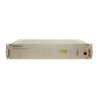
oscilloquartz OSA 5240 User Manual (106 pages)
Telecom GPS Receiver
Brand:
oscilloquartz
| Category:
Receiver
| Size: 1.58 MB
Table of Contents
Table of Contents
5
1 Introduction
11
About this Manual
13
Copyright Notice
13
Reading Guide
14
Safety Instructions
15
Warranty
18
Certification
19
2 Product Overview
21
Introduction
23
Reliability
23
Bridging
23
Signal Quality
23
Output Configurations
23
Versatility
24
Management
24
Local
24
Remote
24
3 Main Functions
25
System Architecture
27
Figure 3-1 System Architecture
27
Frequency Generation
29
Reference Input Selection
29
Phase Build-Out
29
Figure 3-2 Schematic Presentation of the Phase Buildout
29
Filtering and Bridging Capability
30
Table 3-1 Telecordia Recommendation GR-1244-CORE
30
Synchronization Outputs
31
Ssm
31
Figure 3-3 Example of Filtering the GPS Synchronization Signal
31
Output Squelch
32
Re-Timing Channels
33
Figure 3-4 Block Diagram of the Re-Timing Function
33
Timecode Output
34
NTP Server
34
IRIG-B Outputs
34
Monitoring & Alarms
34
Power Supply Inputs
35
4 Equipment Description
37
Dimensional Views
37
Front View
39
Top View
39
Figure 4-1 Dimensions - Front View
39
Figure 4-2 Dimensions - Top View
39
Front Panel Description
40
Figure 4-3 Front Panel Description - Example E1
40
Figure 4-4 Front Panel Description - Example T1
40
Table 4-1 Operational / Alarm State- OSA 5240 R1.0E (E1 Model)
41
Table 4-2 Operational / Alarm State- OSA 5240 R1.1E (E1 Model)
42
Table 4-3 Operational / Alarm State- OSA 5240 R1.0T (T1 Model)
43
Table 4-4 Operational / Alarm State- OSA 5240 R1.1T (T1 Model)
44
Rear Panel Layout
45
Connectors Panel Layout (Except Outputs Slots)
45
Figure 4-5 Rear Connector Panel - Example E1
45
Figure 4-6 Rear Connector Panel - Example T1
45
Table 4-5 Rear Connectors Description
45
Outputs Slots - OSA 5240 R1.Xe (E1 Model)
46
Figure 4-7 Rear Output Slots - Example Model E1
46
Table 4-6 E1 Outputs Slot
46
Outputs Slots - OSA 5240 R1.Xt (T1 Model)
47
Figure 4-8 Rear Output Slots - Example Model T1
47
Table 4-7 T1 Output Slots
47
5 Installation
49
Unpacking and Inspection
51
Working Conditions
52
Tools Required
52
Power-Up
53
Connections
54
Figure 5-1 Rear Power Supplies DC Connection Location
54
Figure 5-2 Rear Power Supply AC Connection Location
54
Table 5-1 Voltage Range and Fuses
54
Figure 5-3 DC Connection View
55
Warm-Up
56
Figure 5-4 AC Connection View
56
Connecting the GPS Antenna
57
Figure 5-5 Rear Unit Connection GPS Antenna Location
57
Connecting the Auxiliary Input Reference
58
Auxiliary Input Connection
58
Figure 5-6 Rear Unit Connection AUX Inputs Location
58
Figure 5-7 BNC Aux Input Connector
59
Table 5-2 Aux Input Connector - BNC
59
Timing Extractor - Passive (TEX-P)
60
Figure 5-8 Typical Use of the TEX-P with the OSA 5240 Telecom GPS Receiver
60
Table 5-3 AUX Input Connectors - Sub-D, Wire-Wrap
60
Connecting the Output Signals
61
Output Connections
61
Figure 5-9 Rear Unit Output Signals
61
Output Connectors Pin-Out
62
Table 5-4 Sub-D Output Connectors
62
Table 5-5 Wire-Wrap (2P) Output Connectors
62
Figure 5-10 BNC Output Connectors
63
Table 5-6 Sub-D RS422 Output Connectors
63
Table 5-7 Wire-Wrap (3P) Output Connectors
63
Table 5-8 BNC Output Connections
63
Time Code Output
64
Alarm Contact Output Wire Wrap Adapter
64
6 Configuring the Unit
65
Factory Default Parameters
65
Table 6-1 Factory Default Parameters
67
Configuration
68
7 Remote Operations
69
Features
71
Electrical Alarm Outputs
71
ALARM OUTPUTS" Pin-Out
71
Figure 7-1 Alarm Output
71
Table 7-1 "Alarm Output" Pin-Out
71
Wire-Wrap Adapter
72
Local Management Capabilities
72
Figure 7-2 RS 232 for Local Management Port
72
RS-232C" Pin-Out
73
Table 7-2 RS232 for Local Management Pinout
73
Table 7-3 NULL MODEM Cable
73
Network Management Capabilities
74
Connecting to a Syncview™ Remote Manager
74
Figure 7-3 Remote Management Port
74
8 Maintenance & Troubleshooting
75
Preventive Maintenance
78
Checking the Functional Status of the OSA 5240 Telecom GPS Receiver
78
Visual Status
78
Internal Status
78
Figure 8-1 Remote Management Port
78
Troubleshooting
79
Table 8-1 Troubleshooting
84
Oscilloquartz Contact Information
85
Technical Assistance
85
Sales
86
9 Specifications
87
Input Specifications
89
Table 9-1 Input Specifications
89
Tracking Subsystem Characteristics
90
Table 9-2 Tracking Subsystem Characteristics
90
Output Specifications - OSA 5240 R1.Xe
91
Table 9-3 Output Specifications R1.Xe
91
Output Specifications - OSA 5240 R1.Xt
92
Time Code Outputs
93
Table 9-4 Output Specifications R1.Xt
93
Table 9-5 Time Code Output Specifications
93
Remote Functions
94
Table 9-6 Remote Functions Specifications
94
General Specifications
95
Table 9-7 General Specifications
95
Appendix A : Ordering Information
97
Table 9-8 Ordering E1 Units
97
Table 9-9 Ordering T1 Units
98
Table 9-10 Fuse Ordering Numbers
98
Table 9-11 Ordering Miscellaneous Accessories
99
Glossary
101
Index
103
Document History
105
Advertisement
Advertisement
Related Products
oscilloquartz Categories
Receiver
More oscilloquartz Manuals
Login
Sign In
OR
Sign in with Facebook
Sign in with Google
Upload manual
Upload from disk
Upload from URL