Sign In
Upload
Manuals
Brands
Omron Manuals
Inverter
VS mini J7
Omron VS mini J7 Manuals
Manuals and User Guides for Omron VS mini J7. We have
3
Omron VS mini J7 manuals available for free PDF download: User Manual, Manual
Omron VS mini J7 User Manual (177 pages)
Compact General Purpose Inverter
Brand:
Omron
| Category:
Inverter
| Size: 8.53 MB
Table of Contents
Table of Contents
13
CHAPTER 1 Overview
15
Function
16
Nomenclature
17
Chapter 2 Design
19
Installation
20
Dimensions
20
Installations Conditions
22
Wiring
24
Removing and Mounting the Covers
25
Terminal Block
26
Standard Connections
30
Wiring Around the Main Circuit
31
Wiring Control Circuit Terminals
41
Conforming to EC Directive
43
CHAPTER 3 Preparing for Operation and Monitoring
47
Nomenclature
48
Outline of Operation
49
CHAPTER 4 Test Run
55
Procedure for Test Run
57
Operation Example
59
Chapter 5 Basic Operation
63
Initial Settings
64
V/F Control
65
Setting the Local/Remote Mode
67
Selecting the Operation Command
68
Setting the Frequency Reference
69
Selecting the Frequency Reference
69
Upper and Lower Frequency Reference Limits
70
Adjusting the Analog Input
70
Setting Frequency References through Key Sequences
71
Setting the Acceleration/Deceleration Time
74
Selecting the Interruption Mode
76
Selecting the Reverse Rotation-Prohibit
76
Multi-Function
77
Multi-Function Input
77
Multi-Function Output
81
Multi-Function I/0
77
5-10 Analog Monitor Output
82
Chapter 6 Advanced Operation
83
Setting the Carrier Frequency
84
DC Injection Braking Function
86
Stall Prevention Function
87
Overtorque Detection Function
90
Torque Compensation Function
91
Slip Compensation Function
92
Other Functions
93
Motor Protection Characteristics (N33 and N34)
93
Cooling Fan Operation Function (N35)
94
Momentary Power Interruption Compensation (N47)
94
Fault Retry (N48)
95
Frequency Jump Function (N49 to N51)
96
Frequency Detection Function
97
UP/DOWN Command Frequency Memory (N62)
99
Error History (N78)
101
Chapter 7 Communications
103
RS-422/485 Communications Unit
104
Overview
104
External Dimensions
104
Names of Parts
105
Mouting Procedure
105
Inverter Settings
107
Setting the Communications Conditions
107
Operation Command Selection (N02)
110
Frequency Reference Input Selection (N03)
110
Setting the Multi-Function Inputs (N36 to N39)
111
Message Communications Basic Format
112
DSR Message and Response
115
Data Read (Function Code: 03 Hex)
115
Data Write/Broadcast Data Write (Function Code: 10 Hex)
117
Loop-Back Test (Function Code: 08 Hex)
120
Enter Command
122
Setting the Communications Data
123
Register Number Allocations in Detail
125
I/O Function
125
Monitor Functions
126
Communications Error Codes
129
Self-Diagnostic Test
130
Chapter 8 Communications
131
Protective and Diagnostic Functions
132
Fault Detection (Fatal Error)
132
Warning Detection (Nonfatal Error)
135
Troubleshooting
137
Parameters Fail Set
137
Motor Fails to Operate
137
Motor Rotates in the Wrong Direction
138
Motor Outputs no Torque or Acceleration Is Slow
139
Motor Deceleration Is Slow
139
Motor Burns
139
Controller or am Radio Receives Noise When Inverter Is Started
140
Ground Fault Interrupter Is Actuated When Inverter Is Started
140
Mechanical Vibration
140
8-2-10 Motor Rotates after Output of Inverter Is Turned off
141
8-2-11 Detects OV When Motor Starts and Motor Stalls
141
8-2-12 Output Frequency Does Not Reach Frequency Reference
141
8-2-13 Inverter Does Not Run
141
Maintenance and Inspection
142
Chapter 9 Specifications
145
Inverter Specifications
146
Specifications of Accessories
149
List of Accessories
149
Adapter Panel
150
Fan Unit
151
RS-422/485 Communications Unit
151
Digital Operator
152
DC Reactor
153
Digital Operator Case
153
Digital Operator Connection Cable
153
DIN Track Mounting Bracket
154
9-2-10 AC Reactor
155
Option Specifications
156
EMC-Compatible Noise Filter
156
Chapter 10
159
List of Parameters
159
Chapter 11
173
Using the Inverter for a Motor
173
Advertisement
Omron VS mini J7 User Manual (123 pages)
Compact General Purpose Inverter
Brand:
Omron
| Category:
Inverter
| Size: 4.59 MB
Table of Contents
Notes for Safe Operation
3
Table of Contents
12
Receiving
15
Checking the Name Plate
15
Identifying the Parts
16
Mounting
17
Choosing a Location to Mount the Inverter
17
Mounting Dimensions
18
Mounting/Removing Components
19
Wiring
20
Wiring Instructions
20
Wire and Terminal Screw Sizes
21
Wiring the Main Circuit
24
Wiring the Control Circuit
25
Wiring Inspection
26
Operating the Inverter
27
Test Run
27
Operating the Digital Operator
29
LED Description
31
Simple Data Setting
35
Programming Features
36
Constant Set-Up and Initialization
36
Selecting V/F Pattern
37
Switching LOCAL/REMOTE Modes
40
Selecting Run/Stop Commands
41
Selecting Frequency Reference
42
Setting Operation Conditions
43
Reverse Run Prohibit
43
Multi-Step Speed Selection
43
Operating at Low Speed
44
Adjusting Speed Setting Signal
45
Adjusting Frequency Upper and Lower Limits
47
Using Two Accel/Decel Times
47
Automatic Restart after Momentary Power Loss
48
Soft-Start Characteristics
49
Torque Detection
50
Frequency Detection
52
Jump Frequencies
53
Continuing Operation by Automatic Fault Reset
53
Operating Coasting Motor Without Trip
54
Holding Accel/Decel Temporarily
55
Using Frequency Meter or Ammeter
56
Calibrating Frequency Meter or Ammeter
56
Reducing Motor Noise or Leakage Current
57
Operator Stop Key Selection
59
Selecting Stopping Method
60
Applying DC Injection Braking
61
Building Interface Circuits with External Devices
62
Using Input Signals
62
Using Output Signals
65
Setting Frequency by Current Reference Input
67
Preventing Motor from Stalling (Current Limit)
69
Decreasing Motor Speed Fluctuation
71
Slip Compensation
71
Motor Protection
72
Motor Overload Detection
72
Selecting Cooling Fan Operation
73
Using MEMOBUS (MODBUS) Communications (Optional)
74
MEMOBUS (MODBUS) Communications
74
Communication Specifications
74
Using Constant Copy Function
75
Constant Copy Function
75
READ Function
77
COPY Function
78
VERIFY Function
80
Inverter Capacity Display
81
Software No. Display
82
Maintenance and Inspection
84
Periodical Inspection
84
Part Replacement
84
Fault Diagnosis
87
Protective and Diagnostic Function
87
Troubleshooting
95
Specifications
98
Standard Specifications (200V Class)
98
Standard Specifications (400V Class)
101
Standard Wiring
104
Sequence Input Connection with NPN/PNP Transistor
106
Dimensions/Heat Loss
109
Recommended Peripheral Devices
111
Constants List
113
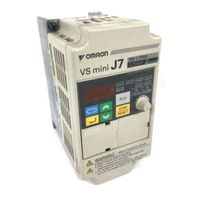
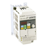
OMRON VS mini J7 Manual (116 pages)
Compact General Purpose Inverter 200V Class 3-phase 0.1 to 4.0kW; 200V Class Single-phase 0.1 to 1.5kW; 400V Class 3-phase 0.37 to 4.0kW
Brand:
OMRON
| Category:
Inverter
| Size: 6.09 MB
Table of Contents
Español
43
General Precautions
3
Safety Information
3
Warning Display
5
Checking the Name Plate
6
Maintenance and Inspection
11
Periodical Inspection
12
Part Replacement
12
Quick Start Guide
15
Control Circuit Terminals
17
Mounting Dimensions
20
Start up and Trial Run
20
Faults and Alarms
27
Table of Contents
43
Terminales del Circuito de Control
45
Inicio y Prueba de Funcionamiento
48
Lista Rápida de Parámetros
52
Monitorización
54
Fallos y Alarmas
55
Estado de Terminal de Entrada/Salida
55
Moniteurs
68
Erreurs Et Alarmes
69
Italiano
71
Terminali Circuito DI Controllo
73
Avvio E Collaudo
76
Elenco Dei Parametri Principali
80
Funzioni DI Monitoraggio
82
Errori E Allarmi
83
Stato Terminali D'ingresso/Uscita
83
Advertisement
Advertisement
Related Products
Omron Varispeed V7 CIMR-V7AZB1P5
Omron Varispeed V7 CIMR-V7AZB2P2
Omron Varispeed V7 CIMR-V7TZB0P705
Omron Varispeed V7 CIMR-V7AZ20P1
Omron Varispeed V7 CIMR-V7AZ20P7
Omron Varispeed V7 CIMR-V7AZ22P2
Omron Varispeed V7 CIMR-V7AZ24P0
Omron Varispeed V7 CIMR-V7AZ40P2
Omron Varispeed V7 CIMR-V7AZ41P5
Omron Varispeed V7 CIMR-V7TZ40P405
Omron Categories
Blood Pressure Monitor
Controller
Accessories
Switch
Inverter
More Omron Manuals
Login
Sign In
OR
Sign in with Facebook
Sign in with Google
Upload manual
Upload from disk
Upload from URL