Omron SYSMAC FHV Series Manuals
Manuals and User Guides for Omron SYSMAC FHV Series. We have 3 Omron SYSMAC FHV Series manuals available for free PDF download: User Manual, Operation Manual
Omron SYSMAC FHV Series User Manual (582 pages)
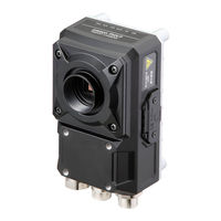
Vision Sensor
Brand: Omron
|
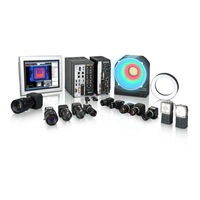
Category: Machine Vision Systems
|
Size: 26.64 MB
Table of Contents
-
-
-
-
All Series33
-
FH-L Series34
-
FHV Series35
-
-
Terminology
39 -
-
Features55
-
-
What Is a Scene
174 -
Creating a Scene
177 -
-
-
Setting Windows303
-
-
Windows
303 -
-
Judgement Pane324
-
Information Pane324
-
Toolbox Pane325
-
Measurement Pane327
-
Error Pane333
-
Label Pane336
-
Troubleshooting363
-
Advanced Usage
439 -
-
Logging in486
-
Logging out487
-
-
What to Do
507 -
Appendices
521-
A-1 Menu List
523 -
-
Measurement528
-
Input Image528
-
A-4-5 Branch529
-
A-6 Image File
541 -
-
A-8-1 FH Series547
-
A-8-2 FHV Series547
-
FH Series547
-
-
Advertisement
Omron SYSMAC FHV Series User Manual (647 pages)
for Communication Settings
Brand: Omron
|
Category: Machine Vision Systems
|
Size: 14.77 MB
Table of Contents
-
-
Overview
25
-
-
Introduction
26 -
-
-
I/O Signals108
-
Command List114
-
Data Output120
-
Timing Chart123
-
-
I/O Signals235
-
Output Items238
-
Command List239
-
Data Output246
-
Timing Chart248
-
-
I/O Signals299
-
Output Items303
-
Command List304
-
Data Output312
-
Timing Chart314
-
-
I/O Signals360
-
Output Items364
-
Command List365
-
Data Output371
-
Timing Chart373
-
-
Output Items403
-
Command Formats405
-
Command List407
-
Output Format411
-
-
I/O Signals442
-
Output Items453
-
Command Formats455
-
Time Charts459
-
Appendices
473 -
-
Command List479

Omron SYSMAC FHV Series Operation Manual (176 pages)
Vision System, for Sysmac Studio
Brand: Omron
|
Category: Industrial Equipment
|
Size: 5.56 MB
Table of Contents
-
Terminology
22 -
-
Overview27
-
-
-
-
Input Image98
-
Measurement98
-
Branch99
-
-
-
Editing an Area103
-
Color Extraction106
-
Color107
-
Binary107
-
List108
-
Help
141 -
-
Limitations
155
-
Troubleshooting
163 -
Appendices
167
Advertisement
Advertisement