Sign In
Upload
Manuals
Brands
Omron Manuals
Processor
SYSMAC CJ2M-CPU1 Series
Omron SYSMAC CJ2M-CPU1 Series PLC CPU Manuals
Manuals and User Guides for Omron SYSMAC CJ2M-CPU1 Series PLC CPU. We have
6
Omron SYSMAC CJ2M-CPU1 Series PLC CPU manuals available for free PDF download: User Manual, Replacement Manual, Datasheet
OMRON SYSMAC CJ2M-CPU1 Series User Manual (640 pages)
CJ2 CPU Unit Software
Brand:
OMRON
| Category:
Software
| Size: 21.12 MB
Table of Contents
Table of Contents
13
Introduction
5
Intended Audience
5
CJ2 CPU Unit Manuals
6
Manual Structure
9
Additional Information
9
Sections in this Manual
11
Table of Contents
13
Safety Precautions
25
Application Precautions
29
Operating Environment Precautions
34
Regulations and Standards
35
Unit Versions of CJ2 CPU Units
37
Related Manuals
42
1 Overview
45
CJ2 CPU Unit Features
45
Overview of CJ2 CPU Units
45
Overview of CJ2 CPU Units
46
Overview
46
Overview
47
CJ2 CPU Unit Features
48
Basic Operating Procedure
55
2 Internal Memory in the CPU Unit
57
Overview
58
Memory Configuration
58
Built-In Flash Memory
58
Built-In Ram
58
Memory Areas and Stored Data
59
Transferring Data from a Programming Device to the CPU Unit
60
CPU Unit Operation
61
CPU Unit Operating Modes
61
CPU Unit Internal Operation
62
Overview
62
Startup Initialization
62
Cycle Time
64
Program Execution
64
I/O Refreshing
66
Processing at Power Interruptions
67
CPU Unit Operating Modes
68
Operating Modes
68
Checking the Operating Mode
69
Changing the Operating Mode
70
Operating Mode Details
74
CPU Unit Initialization
75
Overview of CPU Unit Initialization
76
CPU Unit Initial Settings
76
CPU Unit Initialization
76
Dip Switch
76
Plc Name
78
Routing Tables
79
PLC Setup
82
Creating I/O Tables
83
I/O Tables
83
Automatic Allocation
84
Manual Allocation
84
Setting Routing Tables
85
Routing Tables
85
Local Network Table
86
Relay Network Table
86
Cases in Which Routing Tables Are Required
87
Setting and Transferring Routing Tables
88
Setting Allocated DM Area Words for Special I/O Units
89
Setting Allocated DM Area Words for Special I/O Units and CPU Bus Units
89
Setting Procedure
89
CPU Bus Unit Setup Area
90
Setting Procedure
90
Understanding Programming
91
Programming
93
Programming Overview
93
Program Capacity
95
Basic Ladder Diagram Concepts
96
ST Language
98
SFC Overview
99
Tasks
101
Overview of Tasks
101
Cyclic Tasks
104
Cyclic Task Status
106
Task Control Instructions
107
Interrupt Tasks
110
External Interrupts
117
Designing Tasks
118
Flags Related to Tasks
121
Sections
128
Overview of Sections
128
Function Blocks
130
Features of Function Blocks
130
Function Block Specifications
132
Symbols
135
Overview
135
Types of Symbols
136
Variables in Function Blocks
137
Global Symbols
138
Local Symbols
138
Network Symbols
139
Network Symbols (CJ2H-CPU6@-EIP and CJ2M-CPU3@ Only)
139
Variables in Function Blocks
143
Symbol Data Types
144
Specifying Arrays
145
Automatic Address Allocation to Symbols
149
Instructions
150
Basic Understanding of Instructions
150
Instruction Conditions
151
Instruction Location and Execution Conditions
152
Instruction Variations
153
Execution Conditions
153
Specifying Operands
157
Specifying Operands
159
Data Formats
165
I/O Refresh Timing
169
Cyclic Refresh
169
Index Registers
174
What Are Index Registers
174
Using Index Registers
174
Processing Related to Index Registers
178
Monitoring Index Registers
179
Sharing Index and Data Registers between Tasks
180
Specifying Address Offsets
182
Overview
182
Examples of Address Offset Application
185
Checking Programs
186
Errors During CX-Programmer Input
186
Program Checks with the CX-Programmer
186
Debugging with the Simulator
187
Error Simulation Function
189
Program Execution Check
190
Precautions
193
Condition Flags
193
Special Program Sections
198
I\/O Memory Areas
203
I/O Memory Areas
203
I/O Memory Area Overview
204
I/O Memory Areas
204
I/O Memory Area Structure
206
Holding I/O Memory Values
208
I/O Area
210
Input Bits
210
Output Bits
212
Data Link Area
215
Synchronous Data Refresh Area
216
CPU Bus Unit Area
217
Special I/O Unit Area
218
Serial PLC Link Area
219
Devicenet Area
220
Work Area
221
Holding Area
222
Self-Maintaining Bits
222
Auxiliary Area
224
Temporary Relay Area
225
Data Memory Area
226
Extended Data Memory Area
229
Automatic Address Allocation
229
File Memory
230
Trace Memory
230
Timer Areas
233
Counter Areas
235
Task Flags
236
Index Registers
237
Data Registers
242
Condition Flags
244
Clock Pulses
246
File Operations
249
File Memory
250
File Operations
250
Types of File Memory
250
Initializing File Memory
251
Memory Card Precautions
253
Memory Card Recognition Time
253
Types of Files Stored in File Memory
255
File Types
255
Program/Network Symbol File
255
Parameter File
256
Data File
256
Comment File
257
Program Index File
257
Unit Backup File
257
Creating and Saving Files for File Memory
258
File Memory Operations
259
Types of File Memory Operations
259
Backup Restore Operation
260
File Memory Operating Procedures and File Memory Files
261
Files Automatically Transferred at Startup
261
General-Purpose Files
263
Restrictions on File Use
267
File Sizes
268
Relation between Support Software and File Memory Files
269
I\/O Allocations and Unit Settings
271
I/O Allocations
271
I/O Allocations
272
Automatic Allocation
275
Manual Allocation
279
Allocating First Words to Racks
284
I/O Table Errors and Precautions
287
Setting CPU Bus Units and Special I/O Units
290
Setting Parameters
290
Data Exchange
294
Special I/O Units
294
Fins Commands
295
Cpu Bus Units
296
Plc Setup
299
Overview of the PLC Setup
300
PLC Setup Settings
302
PLC Setup Settings
303
Startup Operation Settings
303
Iom Hold Bit Startup Hold Setting
304
Execution Setting
305
CPU Unit Settings
306
Execute Process
306
Background Execution Settings
310
Retry Counts
311
Timings/Synchronous Settings
312
Watch Cycle Time
312
Scheduled Interrupt Interval
314
Power off Detection Delay Time
315
Power off Interrupt Disabled
316
Special I/O Unit Cyclic Refreshing
317
Disable Siou Cyclic Refresh
317
Basic I/O Unit Rack Response Times
319
Serial Port Settings
321
Peripheral Service
328
Set Time to All Events
328
FINS Protection
329
Settings for Fins Write Protection Via Network
329
10 CPU Unit Functions
331
Clock Functions
333
Times Stored in Memory
334
Power on Clock Data
334
Power Interruption Time
335
Total Power on Time
335
Free-Running Timers
336
Cycle Time/High-Speed Processing
337
Minimum Cycle Time
337
Maximum Cycle Time
338
Monitoring the Cycle Time
339
High-Speed Inputs
339
Background Execution
340
Programming Example
346
High-Speed Interrupt Function
349
Startup Settings and Maintenance
352
Holding Settings for Operating Mode Changes and at Startup
352
Power off Detection Delay Setting
354
Disabling Power off Interrupts
355
RUN Output
356
Automatic Transfer at Startup
357
Unit Management Functions
365
Basic I/O Unit Management
365
CPU Bus Unit Flags/Bits
367
Special I/O Unit Flags/Bits
368
Memory Management Functions
369
Automatic Backup
369
EM File Memory Functions
371
Comment Memory
372
Replacing the Entire Program During Operation
373
Example Programs
376
Security Functions
380
Write-Protection Using the DIP Switch
380
Read Protection Using Passwords
380
Operating Procedure
381
Enabling/Disabling Saving to Memory Cards
383
Enabling and Disabling Program Overwriting
384
Program Operation Protection Using Production Lot Numbers
385
Write Protection from FINS Commands
386
PLC Names
390
Debugging
393
Forced Set/Reset
393
Test Input
394
Differential Monitoring
394
Online Editing
395
Turning off Outputs
397
Tracing Data
398
Storing the Stop Position at Errors
403
Failure Alarm Instructions
404
Simulating System Errors
405
Failure Point Detection
406
Synchronous Unit Operation
408
Overview
408
Application Example
410
Details on Synchronous Unit Operation
411
Synchronous Unit Operation Specifications
414
Synchronous Data Refresh
415
Restrictions in Using Synchronous Unit Operation
419
Application Procedure
421
PLC Setup
422
Writing the Synchronous Interrupt Task
424
Adjusting and Troubleshooting Synchronous Unit Operation
425
Programming Devices and Communications
429
Accessing a PLC from the CX-Programmer
430
Overview
430
System Configurations for Accessible Plcs
432
Accessing a PLC from the CX-Programmer
436
Automatic Online Connection
439
Serial Communications
443
Overview of Serial Communications
443
No-Protocol Communications System
445
Host Link Fins
447
Operating Specifications
449
System Configuration
449
Communications Networks
457
CPU Unit Cycle Time
461
Monitoring the Cycle Time
462
Computing the Cycle Time
464
CPU Unit Operation Flowchart
464
Cycle Time Overview
465
I/O Unit Refresh Times for Individual Units
467
Cycle Time Calculation Example
471
Online Editing Cycle Time Extension
473
I/O Response Time
473
Response Time for Built-In Input Interrupts
474
Response Performance of Serial PLC Links
475
Appendices
477
Instruction Functions
479
A-1-1 Sequence Input Instructions
479
A-1-2 Sequence Output Instructions
481
A-1-3 Sequence Control Instructions
482
A-1-4 Timer and Counter Instructions
486
A-1-5 Comparison Instructions
490
A-1-6 Data Movement Instructions
494
A-1-7 Data Shift Instructions
496
A-1-8 Increment/Decrement Instructions
500
A-1-9 Symbol Math Instructions
500
A-1-10 Conversion Instructions
505
A-1-11 Logic Instructions
511
A-1-12 Special Math Instructions
513
A-1-13 Floating-Point Math Instructions
514
A-1-14 Double-Precision Floating-Point Instructions
518
A-1-15 Table Data Processing Instructions
521
A-1-16 Tracking Instructions
525
A-1-17 Data Control Instructions
526
A-1-18 Subroutine Instructions
530
A-1-19 Interrupt Control Instructions
531
A-1-20 Step Instructions
532
A-1-21 Basic I/O Unit Instructions
532
A-1-22 Serial Communications Instructions
535
A-1-23 Network Instructions
537
A-1-24 File Memory Instructions
539
A-1-25 Display Instructions
540
A-1-26 Clock Instructions
541
A-1-27 Debugging Instructions
542
A-1-28 Failure Diagnosis Instructions
542
A-1-29 Other Instructions
543
A-1-30 Block Programming Instructions
544
A-1-31 Text String Processing Instructions
548
A-1-32 Task Control Instructions
551
A-1-33 Model Conversion Instructions
551
A-1-34 Special Function Block Instructions
552
Instruction Execution Times and Number of Steps
554
A-2-1 Sequence Input Instructions
555
A-2-2 Sequence Output Instructions
555
A-2-3 Sequence Control Instructions
556
A-2-4 Timer and Counter Instructions
557
A-2-5 Comparison Instructions
558
A-2-6 Data Movement Instructions
559
A-2-7 Data Shift Instructions
560
A-2-8 Increment/Decrement Instructions
561
A-2-9 Symbol Math Instructions
561
A-2-10 Conversion Instructions
563
A-2-11 Logic Instructions
565
A-2-12 Special Math Instructions
565
A-2-13 Floating-Point Math Instructions
565
A-2-14 Double-Precision Floating-Point Instructions
567
A-2-15 Table Data Processing Instructions
568
A-2-16 Tracking Instructions
570
A-2-17 Data Control Instructions
570
A-2-18 Subroutine Instructions
571
A-2-19 Interrupt Control Instructions
571
A-2-20 Step Instructions
572
A-2-21 Basic I/O Unit Instructions
572
A-2-22 Serial Communications Instructions
573
A-2-23 Network Instructions
574
A-2-24 File Memory Instructions
574
A-2-25 Display Instructions
574
A-2-26 Clock Instructions
574
A-2-27 Debugging Instructions
575
A-2-28 Failure Diagnosis Instructions
575
A-2-29 Other Instructions
576
A-2-30 Block Programming Instructions
576
A-2-31 Text String Processing Instructions
578
A-2-32 Task Control Instructions
579
A-2-33 Model Conversion Instructions
579
A-2-34 Special Function Block Instructions
579
A-2-35 SFC Instructions
579
A-2-36 Function Block Instance Execution Time
580
Auxiliary Area
582
A-3-1 Read-Only Area (Set by System
582
A-3-2 Read/Write Area (Set by User
605
Details on Auxiliary Area Operation
614
Memory Map of PLC Memory Addresses
617
PLC Memory Addresses
617
A-4 Memory Map of PLC Memory Addresses
617
Memory Map
618
Operation for Power Interruptions
619
A-5-1 Power off Operation
619
Description of Operation
620
A-5-2 Instruction Execution for Power Interruptions
621
Vista
623
A-6-1 Changing Windows Firewall Settings
623
PLC Comparison Charts: CJ-Series and CS-Series Plcs
626
Functions Supported for Unit Versions
630
Index
633
Revision History
637
Advertisement
OMRON SYSMAC CJ2M-CPU1 Series User Manual (425 pages)
CJ2 CPU Unit Hardware
Brand:
OMRON
| Category:
Processor
| Size: 9.04 MB
Table of Contents
Introduction
7
Applicable Products
7
Intended Audience
7
CJ2 CPU Unit Manuals
8
Manual Configuration
9
Hardware User’s Manual (Cat. No. W472)
9
Manual Structure
11
Page Structure
11
Special Information
11
Additional Information
11
Sections in this Manual
13
Table of Contents
15
Application Considerations
20
Suitability for Use
20
Safety Precautions
23
Definition of Precautionary Information
23
Symbols
24
Application Precautions
27
Power Supply
27
Installation
27
Wiring
28
Handling
28
External Circuits
31
Operating Environment Precautions
32
Regulations and Standards
33
Conformance to Shipbuilding Standards
34
Usage Conditions for NK and LR Shipbuilding Standards
34
Unit Versions of CJ2 CPU Units
35
Notation of Unit Versions on Products
35
Confirming Unit Versions with Support Software
35
PLC Information
35
Unit Manufacturing Information
36
Unit Versions and Programming Devices
39
Pull-Down List for PLC Models
39
Troubleshooting Problems with Unit Versions on the CX-Programmer
40
Related Manuals
41
Overview
43
Overview of CJ2 CPU Units
44
CJ2H CPU Units
45
CJ2M CPU Units
45
Overview
45
CJ2 CPU Unit Features
46
Fast, with Large Memory Capacity
46
High-Speed Processing
46
Built-In Ethernet/Ip Port
47
Built-In USB and Ethernet/Ip Ports
47
General-Purpose Networks for Support Software Interface
47
High-Speed, High-Capacity Data Links with User-Set Refresh Cycles
47
Access from Host Devices Is Enabled Using Tags
48
Network Symbols (Tags) for Flexible Support of Program Changes
48
Tag Access
48
Easier Programming
49
Synchronous Unit Operation
49
Create and Use Data Structures
50
Improved Debugging
51
Add a Serial Option Board (CJ2M-CPU3@ Only)
52
Use Pulse I/O and Interrupt Inputs (CJ2M CPU Units Only)
53
Basic Operating Procedure
54
Connecting Online to the PLC
54
I/O Allocations
54
Setting Devices and Hardware
54
General Specifications
55
Performance Specifications
56
Index
57
Function Specifications
63
Basic System Configuration and Devices
71
Expanded System Configuration
71
Basic System Configuration
72
CPU Rack
72
Expansion Racks
72
Pulse I/O Modules (CJ2M CPU Unit Only)
77
Serial Option Boards (CJ2M-CPU3@ Only)
77
CJ-Series Power Supply Units
77
Memory Cards
78
I/O Control Unit
78
End Cover
78
Maximum Number of Expansion Racks
81
Units
82
Configuration Units
84
Maximum Number of Units
84
Models of Configuration Units
84
CJ-Series Basic I/O Units
85
Input Units
85
Output Units
86
Mixed I/O Units
87
CJ-Series Special I/O Units
88
Calculating Unit Current Consumption
92
Maximum Current and Power Supplied by Power Supply Units
92
Example Calculations
93
Additional Information
94
Rack Current Consumption and Width Display
94
Calculating Power Consumption
95
Basic PLC Power Consumption (W_PLC)
95
Basic I/O Unit Power Consumption (W_IO_ONOFF)
95
Calculation Examples
96
Average Power Consumption (W)
96
Expanded System Configuration
97
Serial Communications
97
System Configuration Example
98
Communications Networks
99
Communications Network Systems
99
Communications Network Overview
100
Nomenclature and Functions
101
CPU Units
102
CPU Section
102
Nomenclature and Functions
102
CPU Unit Status Indicators
104
Memory Card Indicators
105
DIP Switch
106
Display and Indicators for Built-In Ethernet/Ip Port
108
Built-In Ethernet/Ip Section (CJ2H-CPU6@-EIP and CJ2M-CPU3@ Only)
108
Seven-Segment Display
109
Status Indicators: MS, NS, COMM, 100M, and 10M
109
Rotary Switches
111
Setting the Unit Number
111
Left/Right Dot Leds
111
Node Address Setting Switches
112
Relationship with IP Address
112
Memory Card
113
Models and Specifications
113
Operating Procedures
113
Before Using a Memory Card
114
Installing the Memory Card
114
Installing and Removing
114
Removing the Memory Card
115
Installing the Memory Card into a Personal Computer
116
Pulse I/O Modules (CJ2M CPU Unit Only)
117
Models and Specifications
117
Part Names and Functions
117
Connecting Pulse I/O Modules to the CPU Unit
118
Pulse I/O Module Detection
118
Pulse I/O Module Status Indicators
119
Mounting an Option Board
120
Serial Option Boards (CJ2M-CPU3@ Only)
120
Overview
120
Power Supply Units
121
Models and Specifications
121
Components
124
AC Input
125
DC Input
125
Lg
125
Gr
125
RUN Output (CJ1W-PA205R Only)
126
Alarm Output (CJ1W-PA205C Only)
126
Selecting a Power Supply Unit
127
Condition 1: Current Requirements
127
Current Consumption at 5 VDC
127
Current Consumption at 24 VDC
127
Basic I/O Units with Terminal Blocks
128
Interrupt Input Units
128
CJ-Series Basic I/O Units
128
Input Signal Width
129
Thirty-Two/Sixty-Four-Point Basic I/O Units with Connectors
130
Sixty-Four-Point Units
131
I/O Control Units and I/O Interface Units
132
System Configuration
132
Component Names
132
Support Software
133
4-1 Support Software
134
CX-One FA Integrated Tool Package
134
Support Software
134
CX-Programmer
135
CX-Integrator
136
Network Configurator
136
Connection Methods
137
Connecting by USB
137
Connecting Cable
137
Before Connecting
137
CX-Programmer Settings
138
Restrictions on Connecting by USB
138
Connecting by RS-232C
139
Setting the Communications Protocol
140
Connecting to Ethernet (CJ2H-CPU6@-EIP and CJ2M-CPU3@ Only)
141
Installation
145
Fail-Safe Circuits
146
Managing CPU Unit Errors
146
Managing Output Malfunctions
146
Order of Powering up the CPU Unit and Controlled System
146
Electrical Diagram
147
Emergency Stop Circuit
147
Interlock Circuits
147
Accessibility for Operation and Maintenance
148
Improving Noise Resistance
148
Installation and Wiring Precautions
148
Installation in Cabinets or Control Panels
148
PLC Orientation
149
Control Panel Installation Dimensions
150
Installation in a Control Panel
150
Routing Wiring Ducts
151
Wiring Ducts
151
Assembled Appearance and Dimensions
152
20-MM-Wide Units
153
Design Example for Width W
155
Installation Height
156
Connecting PLC Components
157
DIN Track Installation
159
DIN Track and Accessories
160
Connecting CJ-Series Expansion Racks
161
CS/CJ-Series I/O Connecting Cables
161
Cable Connections
162
Connecting the Simple Locking Connectors
162
AC Power Source
164
AC Power Supply Units
164
Isolation Transformer
164
Power Supply Wiring
164
Crimp Terminals
165
DC Power Supplies
166
Power Supply Capacity
166
Wiring in Which the 24-V Power Supply will Short
166
Grounding
167
Output Specifications
168
PLC Input Unit Wiring Example
169
External Display Device Connection Example
170
Electric Wires
171
Wiring CJ-Series Basic I/O Units with Terminal Blocks
171
Wiring Basic I/O Units with Connectors
173
Using User-Made Cables with Connector
174
Wire Size
175
Wiring Procedure
175
Connecting Pulse I/O Modules to External I/O Devices
177
Connecting Pulse I/O Modules to External I/O Devices (CJ2M CPU Unit Only)
177
Connecting to Connector-Terminal Block Conversion Units or I/O Relay Terminals
177
Connecting I/O Devices
179
DC Input Units
179
Input Devices
179
AC Input Units
180
Precautions When Connecting a Two-Wire DC Sensor
180
Output Short-Circuit Protection
182
Output Surge Current
182
Output Wiring Precautions
182
Transistor Output Residual Voltage
182
Connecting through an Ethernet Cable (CJ2H-CPU6@-EIP and CJ2M-CPU3@ Only)
183
Precautions on Laying Twisted-Pair Cable
183
Connecting the Cable
184
Ethernet Connectors
184
Control Panel Installation
186
Temperature
186
Natural Cooling
186
High Temperatures
186
Forced Air Circulation (by Fan in Closed Panel)
187
Room Cooling
187
Low Temperatures
187
Humidity
188
Vibration and Shock
188
Atmosphere
188
Electrical Environment
189
Arrangement of PLC and Units
189
PLC Installation Location
189
Input Signal Noise Countermeasures
190
Power Supply System Diagram
190
Wire Layout for the Power Supply System
190
Wiring External I/O Signal Lines
190
External Wiring
191
Wiring Routes
191
Parallel Wiring (Single Phase)
192
Partitioning Methods for Signal and Power Supply Cables
192
Wiring Methods
192
Example: Separating PLC from Power Lines
193
Other Precautions
193
Grounding Methods and Precautions
194
Principles of One-Point Grounding
194
Grounding for AC Power Supply Units
195
PLC Ground Terminals
195
Precautions When Grounding
195
Shielded Cable Ground
195
Troubleshooting
197
CPU Unit Errors
198
Errors and Remedies
198
Checking Errors
198
Checking the Indicators
198
Checking Error Status with the CX-Programmer
199
Checking Detailed Status
199
Reading Error Log Information
199
Error Log Information
200
Checking Error Log Information
200
CX-Programmer PLC Error Window
200
Directly Monitoring the Area Where Error Log Information Is Stored
200
I/O Table Verification
201
Types of Errors
202
Handling Errors
203
Power Supply Errors
203
CPU Standby Errors
204
Recovery Processing Flow
204
Error Causes and Remedies
204
CPU Reset
205
Cpu Errors
206
Communications Error (Peripheral (USB) Port)
207
Communications Error (Serial Port (RS-232C))
207
Cycle Time Exceeded Error (Fatal Error)
208
I/O Bus Error (Fatal Error)
209
I/O Setting Error (Fatal Error)
211
Memory Error (Fatal Error)
212
Basic I/O Error (Non-Fatal Error)
214
Option Board Errors
215
Battery Error (Non-Fatal Error)
216
CPU Bus Unit Error (Non-Fatal Error)
217
Special I/O Unit Error (Non-Fatal Error)
218
Special I/O Unit Setting Error (Non-Fatal Error)
219
Error Causes and Remedies for Synchronous Unit Operation Settings
220
Checking Built-In Ethernet/Ip Port Error Status
221
Troubleshooting Built-In Ethernet/Ip Port Errors (CJ2H-CPU6@-EIP and CJ2M-CPU3@ Only)
221
Checking Error Status at the Ethernet/Ip Port Seven-Segment Display
222
Errors Related to CPU Unit Data Exchange
222
Errors Related to the CPU Unit
222
Errors Related to the Control Bits
222
Errors Related to the Tag Data Links
223
Errors Related to Memory Access
223
Errors Related to the Network
223
Errors Related to Units
223
Non-CPU Unit Errors and Remedies
224
Error Causes and Remedies
224
Connecting Via the Peripheral (USB) Port
227
CX-Programmer Connections
227
Connecting Via the Serial Port
229
Inspection and Maintenance
231
Inspection Points
232
Periodic Inspection Points
232
Tools Required for Inspections
233
Unit Replacement Precautions
234
Replacing the Battery
235
Battery Replacement
235
Purpose of the Battery
235
Battery Service Life and Replacement Period
235
Low Battery Indicators
236
Replacement Battery
236
Replacement Procedure
236
Operation When Battery Is Exhausted or Not Installed
238
Continuing Operation
238
Saving Data
238
Setup Method
239
Power Supply Unit Replacement Time
240
Power Supply Unit Replacement Notification Module
240
Power Supply Unit with Replacement Notification
240
Principle of Replacement Notification
240
Alarm Output (Replacement Notification Output)
241
Function
241
Replacement Notification Function Displays
241
Display and Alarm Output Operation
242
Maintenance Function Using the TEST Switch
242
Normal Display: Replacement Notification Display
242
Operation at Power off
243
Operation When Turning on the Power
243
Operation When TEST Switch Is Pressed
244
Self-Diagnostic Function
244
Comparison between the CJ1W-PA205C and CJ1W-PA205R
245
Backup Operations
247
Backing up Data
248
Using a Computer to Back up Data to the Computer
248
Using a Computer to Back up Data
249
PLC Backup Tool
249
Applicable Units
249
Applicable Data
249
PLC Backup Tool Operations
250
Restrictions
250
Starting the PLC Backup Tool
250
Comparing Data
251
Restoring Data
252
Simple Backup
253
Overview
253
Backing up Data from the CPU Unit to the Memory Card
254
Restoring Data from the Memory Card to the CPU Unit
254
Operating Procedures
254
Comparing Data in the Memory Card and CPU Unit
255
Verifying Backup Operations with Indicators
256
Related Auxiliary Bits/Words
258
Time Required for Simple Backup
258
Data Backed up Using Simple Backup
258
Symbol Tables, Comments, and Program Index Files
259
Parameter Files
259
Data
259
Unit Backup Data
260
Precautions for Correct Use
262
A-1 Specifications of Basic I/O Units
264
A-1-1 Overview of Units
264
Basic Output Units
265
Basic Mixed I/O Units
266
Reading Terminal Connection Diagrams
266
Basic Input Units with Terminal Blocks
267
CJ1W-ID201 DC Input Unit
267
CJ1W-ID211 DC Input Unit (24 VDC, 16 Points)
268
CJ1W-ID212 DC Input Unit (24 VDC, 16 Points)
269
CJ1W-ID231 DC Input Unit (24 VDC, 32 Points)
270
CJ1W-ID232 DC Input Unit (24 VDC, 32 Points)
271
CJ1W-ID233 DC Input Unit (24 VDC, 32 Points)
272
CJ1W-ID261 DC Input Unit (24 VDC, 64 Points)
274
CJ1W-ID262 DC Input Unit (24 VDC, 64 Points)
275
CJ1W-IA201 AC Input Unit (200 VAC, 8 Points)
277
CJ1W-IA111 AC Input Unit (100 VAC, 16 Points)
278
CJ1W-INT01 Interrupt Input Unit (16 Points)
279
CJ1W-IDP01 Quick-Response Input Unit (16 Points)
280
CJ1W-OA201 Triac Output Unit (8 Points)
284
CJ1W-OD201 Transistor Output Unit (8 Points)
285
CJ1W-OD203 Transistor Output Unit (8 Points)
286
CJ1W-OD211 Transistor Output Unit (16 Points)
287
CJ1W-OD213 Transistor Output Unit (16 Points)
288
CJ1W-OD231 Transistor Output Unit (32 Points)
289
CJ1W-OD233 Transistor Output Unit (32 Points)
291
CJ1W-OD234 Transistor Output Unit (32 Points)
293
CJ1W-OD261 Transistor Output Unit (64 Points)
295
CJ1W-OD263 Transistor Output Unit (64 Points)
297
CJ1W-OD202 Transistor Output Unit (8 Points)
299
CJ1W-OD204 Transistor Output Unit (8 Points)
301
CJ1W-OD212 Transistor Output Unit (16 Points)
302
CJ1W-OD232 Transistor Output Unit (32 Points)
303
CJ1W-OD262 Transistor Output Unit (64 Points)
305
CJ1W-MD231 DC Input/Transistor Output Unit
307
CJ1W-MD233 DC Input/Transistor Output Unit
309
CJ1W-MD263 DC Input/Transistor Output Unit
313
CJ1W-MD232 DC Input/Transistor Output Unit
315
CJ1W-MD563 TTL I/O Unit (32 Inputs/32 Outputs)
317
A-1-3 Precautions on Contact Output Units
319
Contact Current Vs. Service Life Characteristic
319
Inductive Load
319
Service Life Expectancy of CJ1W-OC201/211 Relays
319
Connecting Connector-Terminal Block Conversion Units and I/O Relay Terminals
321
Connection Patterns for I/O Relay Terminals
322
Combinations of Connections
323
Connections to Connector-Terminal Block Conversion Units
323
Connections to I/O Relay Terminals
328
Connector-Terminal Block Conversion Unit Connection Diagrams
331
Inputs and Outputs
343
Connection Diagrams for I/O Relay Terminals
351
G7TC I/O Relay Terminals
351
G70D-V Relay Terminals
352
G70D Relay Terminals
353
G70R Relay Terminals
354
G70A-ZOC16 Relay Terminal Socket
355
Dimensions
356
A-2 Dimensions
356
A-2-1 CJ2H CPU Units
356
A-2-2 CJ2M CPU Units
357
Power Supply Units
358
A-2-4 Basic I/O Units
360
32-Point Units (24-VDC Input/Transistor Output Units)
361
A-2-5 I/O Control Unit and I/O Interface Unit
363
A-2-6 I/O Memory Card
363
A-2-7 Pulse I/O Modules (CJ2M CPU Unit Only
363
A-2-8 Serial Option Boards (CJ2M-CPU3@ Only
364
CP1W-CIF01 RS-232C Option Board
364
CP1W-CIF11 RS-422A/485 Option Board
364
CP1W-CIF12 RS-422A/485 Option Board
364
Fatal and Non-Fatal Error Details
365
Fatal Errors
365
Table of Fatal Errors
366
A-3-2 Non-Fatal Errors
370
Table of Non-Fatal Errors
371
A-4-1 Serial Port Interface Types and Specifications
373
Connecting to a Serial Port on the CPU Unit
373
CPU Unit Built-In RS-232C Interface Specifications
373
Communications Specifications
374
CP1W-CIF01 RS-232C Option Board Specifications
374
Converting Built-In RS-232C to RS-422A/485
375
RS-422A/485 Interface Specifications
375
CJ1W-CIF11 RS-422A Converter
376
DIP Switch Settings
376
Electric Specifications
376
RS-232C Connector
376
NT-AL001 RS-232C/RS-422A Link Adapter
377
Wiring the Recommended Cable (XW2Z-070T-1/XW2Z-200T-1)
378
1:1 Connections Via RS-232C Port
379
A-4-2 Connection Examples
379
Connection Example for the Host Link Serial Communications Mode
379
Host Computer (Host Link or Tool Bus)
379
1:N Connections Via RS-232C Port
380
DIP Switch Settings on the NT-AL001 Link Adapter
381
Wiring with XW2Z-@@0T-1 (10 Conductors)
381
RS-422A/485 Ports with 1:1 Connection
382
RS-422A/485 Ports with 1:N Connections
383
Direct Connection from RS-232C to RS-232C
384
OMRON PT (Host Link or 1:N NT Link)
384
RS-422A/485 Ports with 1:N, 2-Wire Connections
385
RS-422A/485 Ports with 1:N, 4-Wire Connections
385
General-Purpose External Devices (No-Protocol or Serial Gateway)
386
Connecting to E5CK Temperature Controllers
387
Examples of 1:1 Connections to RS-232C Ports
387
Connecting to Modems
388
Using an NT-AL-001 RS-232C/RS-422A Link Adapter
388
Examples of 1:N Connections to RS-232C Ports
389
Examples of 1:1 Connections to RS-422A/485 Ports
390
Examples of 1:N Connections to RS-422A/485 Ports
391
Connecting with RS-422A Converters
392
Connection Example
393
Connections to RS-232C Ports
393
A-4-3 Applicable Connectors and Recommended Cables
394
Connections for Echoback Test
394
Example for CJ2H CPU Unit
394
Examples of Recommended RS-232C Wiring
394
Applicable Connector and Recommended Cables
395
CPU Unit Connector
395
Personal Computer Connector for IBM PC/AT Computer
395
Preparing the Cable
396
Connecting the Shield Line to the Hood (FG)
396
Not Connecting the Shield to the Hood (FG)
396
Soldering
397
Assembling the Hood
397
Example of Recommended RS-422A/485 Wiring
398
Connections to the CPU Unit
398
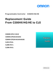
Omron SYSMAC CJ2M-CPU1 Series Replacement Manual (54 pages)
Programmable Controllers
Brand:
Omron
| Category:
Controller
| Size: 1.71 MB
Table of Contents
Related Manuals
3
Dimensions and Weights
5
Performance Data
5
Application Considerations
6
Table of Contents
7
1 Performance Specifications
8
CQM1H/CJ2M Specifications Comparison
8
CJ1M/CJ2M Specifications Comparison
9
CJ1G/CJ2M Specifications Comparison
10
2 System Configurations
11
CQM1H/CJ2M System Comfiguration Comparison
11
CJ1M/CJ1G/CJ2M System Comfiguration Comparison
13
3 Memory Area
14
CQM1H/CJ2M Memory Area Comparison
14
CJ1M/CJ1G/CJ2M Memory Area Comparison
16
4 I/O Area Allocation
18
5 Instructions
20
High-Speed Counter/Pulse Output Instruction
20
I/O Instructions
36
Model Conversion Instructions
41
6 Example of Converting Ladder Program by CX-Programmer
42
Appendix
46
Instruction Operations
46
Condition Flag Operations
49
Advertisement
Omron SYSMAC CJ2M-CPU1 Series Replacement Manual (38 pages)
From C200HX/HG/HE to CJ2
Brand:
Omron
| Category:
Controller
| Size: 1.55 MB
Table of Contents
Table of Contents
10
Work Flow
11
Selecting the Replacement Method
12
Selecting the Model
15
Reading Data from C200HX/HG/HE
20
Converting the Program for CJ2
22
Writing Data to CJ2
24
Appendix
26
Appendix A. Instructions Converted by Change Model on CX-Programmer
26
Appendix B. Change of Unit Area Allocation
29
Appendix C. Change in PLC Settings
29
Appendix D. Change of Execution Timing Etc
29
Appendix E. Table of Input/Output Units
30
Omron SYSMAC CJ2M-CPU1 Series Replacement Manual (36 pages)
From C200HS to CJ2
Brand:
Omron
| Category:
Controller
| Size: 1.53 MB
Table of Contents
Table of Contents
10
Work Flow
11
Selecting the Replacement Method
12
Selecting the Model
15
Reading Data from C200HS
19
Converting the Program for CJ2
21
Writing Data to CJ2
23
Appendix
25
Appendix A. Instructions Converted by Change Model on CX-Programmer
25
Appendix B. Change of Unit Area Allocation
27
Appendix C. Change in PLC Settings
27
Appendix D. Change of Execution Timing Etc
27
Appendix E. Table of Input/Output Units
28
OMRON SYSMAC CJ2M-CPU1 Series Datasheet (24 pages)
CJ2 Series PLCs
Brand:
OMRON
| Category:
Controller
| Size: 2.71 MB
Table of Contents
Specifications
10
General Specifications
10
Performance Specifications
10
Ordering Information
16
Advertisement
Related Products
Omron CJ2M-CPU11/31
Omron CJ2M-CPU12/32
Omron CJ2M-CPU13/33
Omron CJ2M-CPU14/34
Omron CJ2M-CPU15/35
OMRON CJ2H-CPU64 -
OMRON SYSMAC CJ2H-CPU64-EIP
OMRON SYSMAC CJ2H-CPU65-EIP
OMRON SYSMAC CJ2H-CPU66-EIP
OMRON SYSMAC CJ2H-CPU67-EIP
Omron Categories
Blood Pressure Monitor
Controller
Accessories
Switch
Inverter
More Omron Manuals
Login
Sign In
OR
Sign in with Facebook
Sign in with Google
Upload manual
Upload from disk
Upload from URL