Sign In
Upload
Manuals
Brands
Omron Manuals
Servo Drives
R88D-KN15F-ECT-L
Omron R88D-KN15F-ECT-L Manuals
Manuals and User Guides for Omron R88D-KN15F-ECT-L. We have
1
Omron R88D-KN15F-ECT-L manual available for free PDF download: User Manual
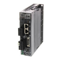
Omron R88D-KN15F-ECT-L User Manual (627 pages)
AC SERVOMOTORS/SERVO DRIVES G5-series WITH BUILT-IN EtherCAT COMMUNICATIONS Linear Motor Type R88L-EC Series; R88D-KN*-ECT-L Series
Brand:
Omron
| Category:
Servo Drives
| Size: 34.6 MB
Table of Contents
Outline
34
What Is Ethercat?
35
System Configuration
36
Names and Functions
38
Servo Drive Functions
39
System Block Diagram
40
Unit Versions
44
Servo System Configuration
46
How to Read Model Numbers
48
Linear Motor
49
Model Tables
51
Servo Drive and Linear Motor Combination Tables
52
Cable and Peripheral Device Model Tables
54
External and Mounting Dimensions
56
Linear Motor Dimensions
64
External Regeneration Resistor Dimensions
71
Reactor Dimensions
72
Mounting Bracket Dimensions
75
Servo Drive Specifications
78
Characteristics
79
Ethercat Communications Specifications
81
Control I/O Specifications (CN1)
82
Control Input Circuits
84
Control Input Details
85
Control Output Circuits
87
Control Output Details
88
External Encoder Specifications
92
External Encoder Connector Specifications (CN4)
93
Analog Monitor Connector Specifications (CN5)
97
USB Connector Specifications (CN7)
98
Overload Characteristics (Electronic Thermal Function)
101
Linear Motor Specifications
104
Performance Specifications of Iron-Core Linear Motors
105
Iron-Core Linear Motor Speed - Force Characteristics
108
Temperature Sensor Specifications of Iron-Core Linear Motors
111
General Specifications of Ironless Linear Motors
112
Ironless Linear Motor Speed - Force Characteristics
115
Temperature Sensor Specifications of Ironless Linear Motors
120
Cable Specifications
121
Cable and Connector Specifications
122
External Encoder Cable Specifications
123
Connector Specifications
124
Ethercat Communications Cable Specifications
125
Analog Monitor Cable Specifications
128
Control Cable Specifications
129
External Regeneration Resistor Specifications
134
Reactor Specifications
135
Installation Conditions
138
Iron-Core Linear Motor Installation Conditions
140
Ironless Linear Motor Installation Conditions
146
Wiring
150
Main Circuit and Linear Motor Connections
154
Terminal Block Wire Sizes
158
Terminal Block Wiring Procedure
160
Wiring Conforming to EMC Directives
162
VAC Input Servo Drive Models
163
Noise Reduction
165
Selecting Connection Components
169
Regenerative Energy Absorption
183
Servo Drive Regeneration Absorption Capacity
185
Regenerative Energy Absorption with an External Regeneration Resistor
186
Connecting an External Regeneration Resistor
187
Display Area and Settings
192
Status Indicators
193
Structure of the CAN Application Protocol over Ethercat
194
Ethercat State Machine
195
Process Data Objects (Pdos)
196
Sync Manager PDO Assignment Settings
197
Variable PDO Mapping
199
Multiple PDO Mapping
200
Service Data Objects (Sdos)
202
Synchronization with Distributed Clocks
203
Emergency Messages
204
Sysmac Device Features
205
Cyclic Synchronous Position Mode
210
Related Objects
211
Block Diagram for Position Control Mode
212
Cyclic Synchronous Velocity Mode
213
Related Objects
214
Block Diagram for Speed Control Mode
215
Cyclic Synchronous Torque Mode
216
Related Objects
217
Related Functions
218
Profile Position Mode
219
Related Objects
220
Description of Function
221
Controlword (6040 Hex) in Profile Position Mode
222
Homing Mode
223
Connecting with OMRON Controllers
224
Sequence I/O Signals
228
Output Signals
231
Positive and Negative Drive Prohibition Functions
234
Overrun Protection
237
Operation Example
238
Backlash Compensation
239
Brake Interlock
241
Operation Timing
242
Electronic Gear Function
246
Operation Example
247
Force Limit Switching
248
Soft Start
250
S-Curve Acceleration or Deceleration Time
251
Gain Switching Function
252
Gain Switching Based on the Control Mode
254
Diagrams of Gain Switching Setting
257
Position Gain Switching Time (3119 Hex)
262
Gain Switching 3 Function
263
Touch Probe Function (Latch Function)
265
Operation Sequences
266
Safe Torque off Function
270
Safety Input Signals
271
External Device Monitor (EDM) Output Signal
272
Operation Example
273
Connection Example
275
Basic Settings
278
Gain Settings
283
Vibration Suppression Settings
294
Analog Control Objects
301
Interface Monitor Settings
306
Extended Objects
317
Special Objects
323
Linear Motor Objects
337
Operational Procedure
348
Preparing for Operation
350
Turning on the Power Supply
352
Preparing the Linear Motor for Operation
354
Linear Motor Setup
359
Outline of Linear Motor Setup
360
Connection from the CX-Drive Via Network
369
Connection from the Sysmac Studio Via Network
371
Trial Operation
373
Trial Operation Via USB Communications from the CX-Drive
374
Analog Monitor
376
Gain Adjustment
379
Gain Adjustment Procedure
380
Realtime Autotuning
381
Operating Conditions
382
Setting Realtime Autotuning
383
Setting Machine Rigidity
384
Objects to be Updated
386
Manual Tuning
389
Position Control Mode Adjustment
390
Damping Control
391
Objects Requiring Settings
392
Operating Procedure
393
Adaptive Filter
395
Operating Conditions
396
Objects to be Set Automatically
397
Notch Filters
398
Objects Requiring Settings
399
Notch Filter Width and Depth
400
Disturbance Observer Function
402
Objects Requiring Settings
403
Friction Force Compensation Function
404
Operating Procedure
405
Feed-Forward Function
406
Operating Procedure
407
Instantaneous Speed Observer Function
409
Objects Requiring Settings
410
Actions for Problems
412
Precautions When a Problem Occurs
413
Warnings
415
Warning List
416
Errors
419
Immediate Stop Operation at Errors
421
Troubleshooting
423
Troubleshooting with the al Status Code
437
Troubleshooting Using the Operation State
438
Periodic Maintenance
445
Servo Drive Life Expectancy
446
Applied Functions
447
A-1 Cia402 Drive Profile
448
A-1-2 Modes of Operation
450
A-1-3 Communications Cycles and Corresponding Modes of Operation
451
A-1-4 Modes of Operation and Applied Functions
452
A-1-5 Changing the Mode of Operation
453
A-1-6 Homing Mode Specifications
461
A-1-7 Object Dictionary
468
A-1-8 Communication Objects
471
A-1-9 PDO Mapping Objects
477
A-1-10 Sync Manager Communication Objects
490
A-1-11 Manufacturer Specific Objects
495
A-1-12 Servo Drive Profile Objects
501
A-2 Object List
523
A-3 Sysmac Error Status Codes
541
A-3-2 Error Description
555
A-4 Response Time in Ethercat Process Data Communications
613
A-4-2 Output Response Time
614
A-5 Ethercat Terminology
615
Advertisement
Advertisement
Related Products
Omron R88D-KN10H-ECT-L
Omron R88D-KN10F-ECT-L
Omron R88D-KN15H-ECT-L
Omron R88D-KN10H-ECT-R
Omron R88D-KN15H-ECT-R
Omron R88D-KN15F-ECT-R
Omron R88D-KN10F-ECT-R
Omron R88D-KN ML2 Sries
Omron R88D-KN01L-ECT
Omron R88D-KN20H-ECT-R
Omron Categories
Blood Pressure Monitor
Controller
Accessories
Switch
Inverter
More Omron Manuals
Login
Sign In
OR
Sign in with Facebook
Sign in with Google
Upload manual
Upload from disk
Upload from URL