Sign In
Upload
Manuals
Brands
Omron Manuals
Control Unit
CJ1G-CPU44H
Omron CJ1G-CPU44H Module CPU Unit Manuals
Manuals and User Guides for Omron CJ1G-CPU44H Module CPU Unit. We have
4
Omron CJ1G-CPU44H Module CPU Unit manuals available for free PDF download: Operation Manual, Operator's Manual, Manual
Omron CJ1G-CPU44H Operator's Manual (274 pages)
CX-Simulator
Brand:
Omron
| Category:
Controller
| Size: 1.6 MB
Table of Contents
Table of Contents
7
Precautions
12
Intended Audience
13
General Precautions
13
Safety Precautions
13
Application Precautions
14
Section 1 Introduction
16
Introduction
16
Summary
17
What Is the CX-Simulator
17
Software Configuration of CX-Simulator
18
Basic Block Diagram
19
Summary of CX-Simulator Functions (Comparisons with Actual PLC)
20
Features
23
Convenient Functions
27
Applicable PLC Models
28
Applicable PLC Models and Computers
28
Computer
28
Required Memory Capacity
29
Checking the Product Package
30
Operation List Arranged by Purpose
31
Program Debugging
31
Program Execution
31
Setting Operation Environment
31
Execute Virtual External Input
32
Monitor the Status
32
Set Network Communications Parameters
32
Set Serial Communications Settings
32
Comparison of CX-Simulator and SYSMAC CS/CJ-Series Plcs
33
Comparison of the CX-Simulator and SYSMAC CS/CJ-Series Plcs
33
Setup
40
Installing and Uninstalling
41
Basic Operation
46
Section 3 Basic Operation
48
Starting Methods for the CX-Simulator
49
Starting and Going Online from the CX-Programmer
50
Basic Window
51
Pop-Up Menu
51
Disconnecting the CX-Simulator from the CX-Programmer
52
Exiting the CX-Simulator from the CX-Programmer
52
Going Online with the CX-Simulator Already Started from CX-Simulator Menus
52
Starting and Exiting from CX-Simulator Menus
53
Starting CX-Simulator
53
Exiting CX-Simulator
54
(CX-Programmer Version 3.0 or Higher)
55
Method 1: Starting and Going Online from the CX-Programmer
55
Outline of Operation Procedure
55
Method 2: Starting from the CX-Simulator Menus
56
Creating a New PLC
59
PLC Setup Wizard
59
Open Existing PLC
66
Folder Used in CX-Simulator
67
Basic Windows Arrangement
69
Each Part of the Windows
69
Basic Windows Transition
70
System Status Setting Window
71
Register PLC Unit
75
Setting Menu of System Status Setting
75
UM Settings
76
PLC Clock Settings
78
PLC Operation Settings
79
Initializing PLC
80
Message Display Window
80
Alarm Display
81
Connecting to the CX-Programmer Version 2.1 or Lower
82
Work CX-Simulator Window
83
How to Connect with CX-Programmer
84
Debug Console Window
87
Menu List of CX-Simulator Debug Console
89
Outline of Basic Operation for Debug Console Menu
90
File] Menu
91
Replay] Menu
95
Help] Menu
104
Step Run] Window
105
Task Control Window
107
I/O Break Condition Settings Window
108
Section 4 Debugging Programs
112
Debugging Programs
112
Debugging Using the CX-Programmer
113
CS/CJ-Series Plc's Modes and Execution Mode
114
Debugging Operation
114
Scan Run
115
Step Run
115
Stop ( )
116
Other Operation
117
Pause ( )
117
Break Setting
118
Operations for Step Run
118
Step Run and Break
118
Break Point
119
Start Point Setting
120
I/O Break Condition Setting
121
Execution Time and Count of Task
126
Task Debugging
126
Task Execution Status
126
Executing Tasks Individually
127
Precautions When Debugging Task
128
Section 5 Debugging Serial Communications
130
Debugging Serial Communications
130
Outline of Serial Communications
131
Serial Communications Settings
134
Access from External Devices Via Serial Communications
138
Serial Communications Connection
138
Access to External Device Using Serial Communications
139
Precautions in Using Serial Communications
139
Connecting PT Via NT Link
141
Examples of Serial Communications Debugging
142
Procedure for Debugging Serial Communications Instructions
142
Debugging by Message Display
143
Debugging by Serial Data File
143
Section 6 Debugging Network Communications
146
Debugging Network Communications
146
Outline of Network Communications
147
Network Communications Setting
150
Network Communications Settings
150
Network Connection
153
Precautions When Using Network Communications
153
Receive FINS Commands from the External Devices Via Network Communications
153
Send FINS Commands to the External Devices Via Network Communications
153
Example of Debugging Network Communications
154
Outline of Debugging Network Communications Instructions
154
Debugging with Display Messages
155
Debugging with Local Communications
155
Available FINS Commands
158
The List of Available FINS Commands
158
Restrictions on FINS Commands
159
Section 7 Connection with Application Programs
160
Outline of Connection
161
What Is Connection with Application
161
Coexist in the same Computer
162
Connection Methods
162
Connection with Application Programs
162
Connection Via Network
164
Section 8 Debugging Using Virtual External Inputs
168
Debugging Using Virtual External Inputs
168
Outline of Virtual External Input Function
169
Debugging Using Virtual External Inputs
170
Outline of Debugging Using Virtual External Inputs
170
Command Log
173
Generating Virtual External Inputs
173
Data Trace File
177
Data Replay File (CSV-Format Text File)
178
Multipoint Data Collection Tool
180
I/O Condition Expressions
183
Messages Displayed in the Error History
183
Ladder Program for Debugging
186
How to Run by Data Replay Tool
187
Running by Virtual External Inputs
187
Replay Using the I/O Condition Tool
191
How to Replay Using the Program Area for Debugging
193
Checking by Time Chart Monitor of the CX-Programmer
195
Checking the Result
195
Checking with Graphing by Excel Using the Data Replay File
196
Section 9 CPU Unit Operation
198
CPU Unit Operation
198
CPU Unit Operation
199
General Flow
199
Startup (Initial) Process
200
Computing Process
201
Overseeing Processing
201
Details of I/O Refresh and Peripheral Servicing
202
Cycle Time
203
Cycle Time and Time
203
Maximum CPU Occupancy and Execution Time
209
Differences with CS/CJ Series
210
I/O Memory Allocation
211
PLC Setup Settings
211
Auxiliary Area (Read-Only Area)
216
Auxiliary Area (Read/Write Area)
238
Differences in CX-Programmer Operation
245
Other Functions
245
Other Precautions
245
Section 10 Troubleshooting
246
Troubleshooting
246
CX-Programmer
247
Debugger and Ladder Engine
247
Error Processing
247
I/O Condition Tool
249
Data Replay Tool
250
Data Trace Recording Tool
251
Alarms and Remedies
252
Connection Impossible from CX-Programmer
254
Other Tips for Troubleshooting
254
A Compare Error Occurs When Editing Online
255
If Network Communications Can Not be Performed
255
A Cycle Time Error Occurs
256
Others
256
Appendix
258
Revision History
270
Advertisement
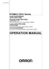
Omron CJ1G-CPU44H Operation Manual (318 pages)
Loop Control Board
Brand:
Omron
| Category:
Controller
| Size: 5.1 MB
Table of Contents
Table of Contents
13
Precautions
23
General Precautions
24
Intended Audience
24
Safety Precautions
25
Operating Environment Precautions
29
Application Precautions
30
EC Directives
32
Other Applicable Directives
32
Section 1 Introduction
35
Introduction
35
Outline
36
Features
39
LCB01/05 Version 1.5 Upgrade Information
41
LCB01/05 Version 2.0 Upgrade Information
43
LCB01/03/05 Version 3.0 Upgrade Information
44
Upgraded Functions for LCB01/05 and LCB03 Version 3.5
46
Basic System Configuration
47
Upgraded Functions for LCB01/05 and LCB03 Version 3.6
47
Application Examples
48
1-1-10 Loop Controller Mechanism
51
1-1-11 Overall Mechanism of Data Exchange
55
1-1-12 Internal Mechanism of Loop Controllers
57
1-1-13 List of Function Blocks
59
1-1-14 Differences between Loop Control Units and Boards
66
1-1-15 Version Upgrade Information
70
Configuration of Instrumentation System
72
Mounting Location
72
Determining the System Configuration
74
Description of Basic System Configuration
79
General Specifications
85
Specifications
85
Function Specifications
87
Outline of PID Block Specifications
91
Software Specifications
94
How to Use Function Blocks for Specific Operations
96
Basic Procedure for Using the Loop Controller
100
Section 2 Components, Installation, and Wiring
105
Components, Installation, and Wiring
105
Names and Functions of Parts
106
Installation
108
Mountable Units
108
Mounting Procedure
108
Handling Analog Input/Output Units
109
Connecting to CX-Process Tool
110
Using Finsgateway
110
Connecting Cables
112
Using CX-Server
112
Section 3 Mechanism of the Loop Controller
115
Mechanism of the Loop Controller
115
Configuration of Function Blocks
116
Preparing Function Block Data Sheets
116
Items Common to All Function Blocks
118
Items Unique to Individual Function Blocks
119
Connecting Function Blocks
122
Description of Operation
125
When Turning the Power on to the PLC
125
Reference: Operations at Power on
133
Details of Hot Start, Cold Start and Stop State
134
Backup/Recovery Operations and Automatic Transfer of ITEM Data
137
Simple Backup of Function Block Data to a Memory Card (LCB01/03/05 Ver. 2.0)
139
Simple Backup of Function Block Data to a Memory Card (LCB01/03/05 Ver. 3.0 or Later)
144
Replacing Function Block Data in the Loop Controller (LCB01/03/05 Ver. 3.5)
150
Indicating Loop Controller Run/Stop (All Function Blocks)
152
(LCB01/03/05 Ver. 3.0 or Later)
153
Starting (RUN/STOP) PID Calculation Only for each Function Block
153
Stop each Function Block Operation and Cancel Operation-Stop
153
3-2-11 Monitoring the Run Status of Function Blocks
154
Wireless Debugging (LCB01/03/05 Ver. 3.0 or Later)
154
3-2-13 Relationship between CPU Unit States and Loop Controller States
158
3-2-14 Specifying the Operation Cycle
159
3-2-15 Conditions for Determining the Operation Cycle
161
3-2-16 Order of Operations
163
3-2-17 about the LCB Load Rate
164
3-2-18 Evaluating the LCB Load Rate at the System Design Stage
164
3-2-19 External I/O Response Cycle on the Overall System
166
Exchanging Data with the CPU Unit
170
Mutual Exchange of Run Status
170
Commands from the CPU Unit to the Loop Controller
178
Exchanging Data
179
Exchanging Data Using SCADA and Other Software
191
Exchanging Data Using SCADA, Pts, and Other Software
191
Duplex Operation of Loop Controllers
201
Loop Controller Duplex Function
201
Outline of Procedure for Using Duplex Mode
202
Restrictions on Duplex Loop Controllers
203
Fail-Safe Countermeasure Guidelines
205
Measures When the Loop Controller Has Stopped Running
205
Measures for a CPU Unit Fatal Error
207
Required Conditions for the Man-Machine Interface
207
Simple Example of Use
209
Simple Example of Use
210
Section 5 Examples of Function Block Combinations
217
Examples of Function Block Combinations
217
Basic Examples of PID Control
218
Multi-Channel PID Control
218
Simple PID Control
218
PID Control for Switching Multiple Set Points
219
PID Control for Switching PID Constants by Three Set Point Zones
220
Ramp Program Control
222
Time-Proportional Control
223
Monitoring and Accumulating Flowrate
224
Cascade Control
225
Examples of Applied Control Types
225
Feedforward Control
228
Sample PI Control
231
Dead Time Compensation
233
How to Use FINS Commands
237
How to Use FINS Commands
238
Description of FINS Commands
240
FINS Commands for Loop Controllers
240
Section 7 Errors and Alarm Troubleshooting
255
Errors and Alarm Troubleshooting
255
Errors and Alarm Troubleshooting
256
Judging Errors by Indicators
256
Errors During Initialization
258
Errors During Normal Operation
261
Error Log Data
262
Execution Error Code List
263
Maintenance
272
Replacing the Loop Control Board
272
Replacing Process-Control CPU Units
274
Replacing Loop-Control CPU Units
275
Using the Flash Memory
276
How to Use the Step Ladder Program Block
277
B How to Use the Sequence Table Block
289
Index
311
Revision History
315
Omron CJ1G-CPU44H Operation Manual (316 pages)
Loop Control Boards, Process-control CPU Units, Loop Controller, Loop-control CPU Units
Brand:
Omron
| Category:
Control Unit
| Size: 2.52 MB
Table of Contents
Table of Contents
13
Precautions
23
General Precautions
24
Intended Audience
24
Safety Precautions
25
Operating Environment Precautions
28
Application Precautions
29
EC Directives
31
Other Applicable Directives
31
Section 1 Introduction
33
Introduction
33
Outline
34
Features
37
LCB01/05 Version 1.5 Upgrade Information
39
LCB01/05 Version 2.0 Upgrade Information
41
LCB01/03/05 Version 3.0 Upgrade Information
42
Upgraded Functions for LCB01/05 and LCB03 Version 3.5
44
Upgraded Functions for LCB01/05 and LCB03 Version 3.6
45
Basic System Configuration
45
Application Examples
46
1-1-10 Loop Controller Mechanism
49
1-1-11 Overall Mechanism of Data Exchange
53
1-1-12 Internal Mechanism of Loop Controllers
55
1-1-13 List of Function Blocks
57
1-1-14 Differences between Loop Control Units and Boards
64
1-1-15 Version Upgrade Information
68
Configuration of Instrumentation System
70
Mounting Location
70
Determining the System Configuration
72
Description of Basic System Configuration
77
Specifications
83
General Specifications
83
Function Specifications
85
Outline of PID Block Specifications
89
Software Specifications
92
How to Use Function Blocks for Specific Operations
94
Basic Procedure for Using the Loop Controller
98
Section 2 Components, Installation, and Wiring
103
Components, Installation, and Wiring
103
Names and Functions of Parts
104
Installation
106
Mountable Units
106
Mounting Procedure (CS1W-LCB01/LCB05 Loop Control Boards Only)
106
Handling Analog Input/Output Units
107
Connecting to CX-Process Tool
108
Using Finsgateway
108
Using CX-Server
110
Connecting Cables
110
Section 3 Mechanism of the Loop Controller
113
Mechanism of the Loop Controller
113
Configuration of Function Blocks
114
Preparing Function Block Data Sheets
114
Items Common to All Function Blocks
116
Items Unique to Individual Function Blocks
117
Connecting Function Blocks
120
Description of Operation
123
When Turning the Power on to the PLC
123
Reference: Operations at Power on
131
Details of Hot Start, Cold Start and Stop State
132
Backup/Recovery Operations and Automatic Transfer of ITEM Data
135
Simple Backup of Function Block Data to a Memory Card (LCB01/03/05 Ver. 2.0)
137
Simple Backup of Function Block Data to a Memory Card (LCB01/03/05 Ver. 3.0 or Later)
142
Replacing Function Block Data in the Loop Controller (LCB01/03/05 Ver. 3.5)
148
Indicating Loop Controller Run/Stop (All Function Blocks)
150
Stop each Function Block Operation and Cancel Operation-Stop
151
Starting (RUN/STOP) PID Calculation Only for each Function Block
151
(LCB01/03/05 Ver. 3.0 or Later)
151
3-2-11 Monitoring the Run Status of Function Blocks
152
Wireless Debugging (LCB01/03/05 Ver. 3.0 or Later)
152
3-2-13 Relationship between CPU Unit States and Loop Controller States
156
3-2-14 Specifying the Operation Cycle
157
3-2-15 Conditions for Determining the Operation Cycle
159
3-2-16 Order of Operations
161
3-2-17 about the LCB Load Rate
162
3-2-18 Evaluating the LCB Load Rate at the System Design Stage
162
3-2-19 External I/O Response Cycle on the Overall System
164
Exchanging Data with the CPU Unit
168
Mutual Exchange of Run Status
168
Commands from the CPU Unit to the Loop Controller
176
Exchanging Data
177
Exchanging Data Using SCADA and Other Software
189
Exchanging Data Using SCADA, Pts, and Other Software
189
Duplex Operation of Loop Controllers
199
Loop Controller Duplex Function
199
Outline of Procedure for Using Duplex Mode
200
Restrictions on Duplex Loop Controllers
201
Fail-Safe Countermeasure Guidelines
203
Measures When the Loop Controller Has Stopped Running
203
Measures for a CPU Unit Fatal Error
205
Required Conditions for the Man-Machine Interface
205
Simple Example of Use
207
Simple Example of Use
208
Section 5 Examples of Function Block Combinations
215
Examples of Function Block Combinations
215
Basic Examples of PID Control
216
Simple PID Control
216
Multi-Channel PID Control
216
PID Control for Switching Multiple Set Points
217
PID Control for Switching PID Constants by Three Set Point Zones
218
Ramp Program Control
220
Time-Proportional Control
221
Monitoring and Accumulating Flowrate
222
Examples of Applied Control Types
223
Cascade Control
223
Feedforward Control
226
Sample PI Control
229
Dead Time Compensation
231
How to Use FINS Commands
235
How to Use FINS Commands
236
FINS Commands for Loop Controllers
238
Description of FINS Commands
238
Section 7 Errors and Alarm Troubleshooting
253
Errors and Alarm Troubleshooting
253
Errors and Alarm Troubleshooting
254
Judging Errors by Indicators
254
Errors During Initialization
256
Errors During Normal Operation
259
Error Log Data
260
Execution Error Code List
261
Maintenance
270
Replacing the Loop Control Board
270
Replacing Process-Control CPU Units
272
Replacing Loop-Control CPU Units
273
Using the Flash Memory
274
How to Use the Step Ladder Program Block
275
B How to Use the Sequence Table Block
287
Index
309
Revision History
313
Advertisement
Omron CJ1G-CPU44H Manual (38 pages)
HOST Link Driver
Brand:
Omron
| Category:
Controller
| Size: 0.73 MB
Table of Contents
Table of Contents
1
System Configuration
3
Selection of External Device
5
Example of Communication Setting
6
Setup Items
24
Cable Diagram
29
Supported Device
35
Device Code and Address Code
37
Error Messages
38
Advertisement
Related Products
Omron CJ1G-CPU42P
Omron CJ1G-CPU42H
Omron CJ1G-CPU43P
Omron CJ1G-CPU44P
Omron CJ1G-CPU45P
Omron CJ1G-CPU43H
Omron CJ1G-CPU45H
Omron CJ1W-ID201
Omron CJ1W-OD203
Omron CJ1W-MD261
Omron Categories
Blood Pressure Monitor
Controller
Accessories
Switch
Inverter
More Omron Manuals
Login
Sign In
OR
Sign in with Facebook
Sign in with Google
Upload manual
Upload from disk
Upload from URL