Sign In
Upload
Manuals
Brands
Omax Manuals
Cutter
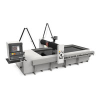
JetMachining Center 60120
Omax JetMachining Center 60120 Cutter Manuals
Manuals and User Guides for Omax JetMachining Center 60120 Cutter. We have
1
Omax JetMachining Center 60120 Cutter manual available for free PDF download: Operator's Manual
Omax JetMachining Center 60120 Operator's Manual (144 pages)
Brand:
Omax
| Category:
Cutter
| Size: 4.1 MB
Table of Contents
About this Manual
3
Purpose
3
Supporting Documentation
3
Organization
3
Table of Contents
5
Figures
9
Safety First
13
Safety Labels
13
Placement of Safety Labels
15
Figure 1-1: Safety Labels for the OMAX Models 2626, 2626|Xp, 2652, 5555, and 55100
15
Figure 1-2: Safety Labels for the OMAX 80160
15
Figure 1-3: Safety Labels for the OMAX 60120
16
Figure 1-4: Safety Labels for the OMAX 80X
16
Safety Precautions
17
Figure 1-5: Safety Labels for the OMAX High-Pressure Pump
17
Pump Safety Requirements
18
Figure 1-6: Sound Level Map of OMAX Jetmachining Center
19
Equipment Safety Features
20
OMAX Jetmachining Center Safety Checklist
21
Introduction
23
OMAX High-Pressure Pump
23
Figure 2-1: OMAX High-Pressure Water Pump
23
Pump Components
24
Front and Right Side Views
24
Figure 2-2: OMAX Variable Speed High-Pressure Pump Front View
24
Figure 2-3: Pump Control Panel Components
24
Figure 2-4: Front Panel Keypad and Display Screen
25
Control Panel Switches
26
Figure 2-5: Pump Control Switches
26
Front View with Front Panel Removed
27
Figure 2-6: Pump with Top Lid Open and Front Panel Removed
27
Top View
28
Side View with End Panel Open
28
Figure 2-7: Pump Top View with Lid Open
28
Figure 2-8: Pump Internal Components on Right Side
28
OMAX Jetmachining Center
29
Major Components of the Jetmachining Centers
29
Figure 2-9: OMAX 80160 Jetmachining Center
29
PC Controller
30
Figure 2-10: the Model 55100 OMAX Jetmachining® Center
30
Figure 2-11: the Jetmachining Center PC Controller
30
Control Panel Switches
31
X-Y Table
31
Figure 2-12: Control Panel Operator Switches
31
Accessories for the OMAX Jetmachining Center
32
Tilt-A-Jet
32
Figure 2-13: the OMAX 80X Jetmachining Center
32
Figure 2-14: OMAX Tilt-A-Jet
32
Precision Optical Locator
33
Waterjet Brick
33
Figure 2-15: OMAX Precision Optical Locator
33
Figure 2-16: Waterjet Brick
33
Solids Removal System
34
Chiller
34
Figure 2-17: OMAX Solids Removal System
34
Figure 2-18: OMAX Inlet Water Chiller
34
Drill Head Attachment
35
Closed Loop Water Recycling System
35
Figure 2-19: OMAX Drill Head Attachment
35
Figure 2-20: Closed Loop Water Recycling System
35
Terrain Follower
36
Figure 2-21: OMAX Terrain Follower Attached to a Tilt-A-Jet
36
Operation
37
Operating the High-Pressure Pump
37
Starting the Pump
37
Stopping the Pump
38
Emergency Shutdown Procedures
38
Setting the Pump RPM
38
Pump Operating Characteristics
39
OMAX Jetmachining Center Overview
39
About Abrasivejet Machining
39
Figure 3-1: the Abrasivejet Nozzle
40
The OMAX Software
41
OMAX Layout Program
41
OMAX Make Program
41
OMAX Interactive Reference
41
Figure 3-2: the Abrasive Waterjet System
41
Drawing the Part Using Layout
42
Setting the Tool Path
42
Making the Part
42
Determining Quality
42
Clamping and Positioning Materials for Cutting
42
Figure 3-3: Quality Examples
42
Using Tabs for Holding Small Parts
43
Figure 3-4: Using Tabs Prevents Small Parts from Falling in the Tank
43
Ensuring Clean and Quiet Machining
44
Keep the Abrasivejet Nozzle under Water
44
Place a Muff on the Abrasivejet Nozzle
44
Keep Extra Sponges on Hand
44
Washing Heavy Garnet Deposits from Parts
44
Figure 3-5: Cutting Nozzle with a Muff Attached
44
Tips for Effective Cutting
45
Setting Soft Limits
46
Auto Homing Your Machine
46
Operating the Jetmachining Center
47
Configuring Your Drawing
47
Figure 3-6: Selecting Auto Home in OMAX Make
47
Cutting Parts
48
Setting up the Hardware
48
Figure 3-7: White Water Tank Internal View
48
Figure 3-8: White Water Tank Location in OMAX Pump
49
Figure 3-9: Verify Correct Mixing Tube Placement
50
Figure 3-10: Use the Homes Menu Option to Initiate an Auto Home
50
Figure 3-11: Use Setup to Enable the Soft Limits
51
Figure 3-12: Pump and Nozzle Test Options
51
Figure 3-13: Example of both Good and Poor Quality Jet Streams
51
Figure 3-14: Comparison of Jet Streams with Different Jewel and Mixing Tube Conditions
52
Figure 3-15: Comparison Spread of Waterjets and Abrasive-Waterjets at Different Health States
52
Figure 3-16: Nozzle Pressure Test Stop Button
53
Figure 3-17: Bimba Valve Abrasive Feed Block
54
Figure 3-18: Setup Menu for Pump and Nozzle Settings
54
Figure 3-19: Settings for Pump and Nozzle
54
Configuring the Make Software
55
Figure 3-20: Event and Relay Timing Displayed Values
55
Figure 3-21: Material Setup Example
55
Cutting the Material
56
Figure 3-22: Cut, Pierce, and Terrain Follower Setting Options
56
Figure 3-23: Nozzle Position Functions
56
Shutting down the Jetmachining Center
57
Figure 3-24: Z-Axis Height
57
Figure 3-25: Pump and Nozzle Test Options
58
Startup Checkoff Sheet
59
Shutdown Checkoff Sheet
60
Maintenance
61
Pump Maintenance
61
General
61
Main Electric Motor Lubrication
61
Changing Crankcase Oil
61
Routine Maintenance Schedule
62
Figure 4-1: Changing the Pump's Crankcase Oil
62
Less Frequent Maintenance Schedule
63
Jetmachining Center Maintenance
63
Rebuilding the Nozzle
64
Nozzle Operation
64
Identifying When to Repair and Rebuild the Nozzle
64
Preparing for Nozzle Repair/Rebuild
64
Removing the Nozzle Mixing Tube
66
Removing the Nozzle Body from the Inlet Body
66
Figure 4-2: Remove the Abrasive Hose from the Nozzle
66
Figure 4-3: Removing the Nozzle Mixing Tube
66
Removing the Filter Seal Assembly from the Inlet Body
67
Removing the Orifice Assembly
67
Figure 4-4: Removing the Nozzle Body from the Inlet Body
67
Figure 4-5: Screwing the Removal Tool into the Filter Seal
67
Figure 4-6: Removing the Orifice Assembly from the Nozzle Body
67
Removing the Mixing Chamber Disc
68
Removing the Mixing Chamber
68
Figure 4-7: Removed Orifice Assembly and Mixing Chamber Disc
68
Figure 4-8: Pressing the Mixing Chamber from the Nozzle Body
68
Removing the Nozzle Body O-Ring
69
Cleaning and Inspecting Nozzle Components
69
Figure 4-9: Removing the O-Ring from the Nozzle Body
69
Figure 4-10: Rinsing Parts with Clean Water
69
Figure 4-11: Cleaning Parts in Ultrasonic Cleaner with White Vinegar
70
Figure 4-12: the Four Primary Nozzle Assembly Components Requiring Inspection
70
Figure 4-13: Good Jewel Orifice
70
Figure 4-14: Chipped Orifice Assembly Jewel
71
Figure 4-15: Plugged Jewel Orifice
71
Figure 4-16: Worn Mixing Chamber Discs
72
Figure 4-17: Worn Mixing Tubes
72
Figure 4-18: Pump and Nozzle Test Options
73
Figure 4-19: Installing the Mixing Tube Upside down to Dislodge a Clogged Opening
73
Reassembling the Nozzle Assembly
74
Nozzle Filter Seal Assembly
74
Figure 4-20: Worn Mixing Chamber
74
Figure 4-21: Purging the High-Pressure System of Contaminates with the Nozzle Removed
74
Figure 4-22: Nozzle Filter Seal Assembly
74
Mixing Chamber
75
Figure 4-23: Filter Seal Assembly Inserted into Inlet Body
75
Figure 4-24: Locating the Mixing Chamber Groove and Abrasive Inlet Hole for Alignment
75
Figure 4-25: Using the Push Tool and Arbor Press to Insert the Mixing Chamber into the Nozzle Body
75
Mixing Chamber Disc and Orifice Assembly
76
Figure 4-26: Installing the O-Ring on the Nozzle Body
76
Figure 4-27: Placing the Mixing Chamber Disc in the Center Bore of the Nozzle Body
76
Figure 4-28: Inserting the Orifice Assembly in the Nozzle Body with the Jewel Side Facing up
76
Nozzle Body
77
Figure 4-29: Applying Blue Goop to the Nozzle Body Inlet Threads
77
Figure 4-30: Installing the Nozzle Body Onto the Nozzle Inlet Body
77
Figure 4-31: Aligning the Nozzle's Abrasive Inlet Hole
77
Figure 4-32: Damage Caused by an Off-Center Orifice
78
Figure 4-33: Tightening the Nozzle's Brass Retainer Nut
78
Figure 4-34: Tightening the Nozzle Body to the Inlet Body
78
Mixing Tube
79
Figure 4-35: Inserting the Mixing Tube into the Nozzle Body
79
Figure 4-36: Placing the Mixing Tube Collet and Nut Onto the Mixing Tube
79
Figure 4-37: Tightening the Mixing Tube Onto the Nozzle Body
79
Nozzle Tests
80
Maximizing Nozzle Life
80
Figure 4-38: Abrasive Damage from Not Using a Nozzle Muff
81
Removing and Reinstalling the Inlet Body on a Tilt-A-Jet
82
Figure 4-39: Removing the Air Hose from the Air Canister Fitting Ring
82
Figure 4-40: Using a 1-1/8" Open-End Wrench to Remove the Air Canister
82
Figure 4-41: Removing the Coil Nipple from the On/Off Valve Body Adapter Fitting
82
Figure 4-42: Removing the 5Mm allen Screws that Secure the On/Off Valve Body
83
Figure 4-43: Removing the On/Off Valve Body with Seat from the Tilting Plate
83
Figure 4-44: Removing the Inlet Body from the Tilting Plate
83
Removing a Stuck Inlet Body
84
Figure 4-45: Installing the Body Removal Tool Post to Remove a Stuck Inlet Body
84
Figure 4-46: Placing the Tube over the Tool Post and Tightening the Flange Nut
84
Figure 4-47: Removing the Brass Inlet Body Retaining Nut with the Spanner Wrench
84
Cleaning the Inlet Body
85
Figure 4-48: Using White Vinegar to Loosen a Stuck Inlet Body
85
Figure 4-49: Tightening Flange Nut to Detach the Inlet Body
85
Figure 4-50: Cleaning the Inlet Body Hole with Brush and Soapy Water
85
Reinstalling the Inlet Body
86
Figure 4-51: Applying Blue Goop to the Inlet Body Male Threads and Bore Diameter
86
Figure 4-52: Hand Tightening the Inlet Body and Aligning to Tilting Plate Hole
86
Figure 4-53: Applying Blue Goop and Anti-Seize Compounds to Valve Body Components
86
Figure 4-54: Correct Placement of the Valve Body Seat into the Valve Body
87
Figure 4-55: Placing the On/Off Valve Body against the Cutting Head Inlet Body
87
Figure 4-56: Tightening the Four Valve Body Screws and Applying Blue Goop to the Gland Nut Threads
87
Removing and Reinstalling a Mini-Maxjet 5 Nozzle Assembly
88
Disassembling a Minijet Nozzle
88
Figure 4-57: Tightening the Coil Nipple to the On/Off Valve Body Adapter Fitting
88
Figure 4-58: Installing the On/Off Valve Air Canister
88
Step 2: Remove the Minijet Nozzle Body from the Inlet Body Extension
89
Step 3: Remove the Inlet Body Extension from the Inlet Body
89
Figure 4-59: Removing the Minijet Nozzle Body from the Inlet Body Extension
89
Figure 4-60: Removing the Inlet Body Extension from the Inlet Body
89
Step 4: Remove the Minijet Dummy Orifice from the Inlet Body
90
Figure 4-61: Inspecting the Body Extension for Erosion Marks
90
Figure 4-62: Inspecting the Dummy Orifice for Erosion Marks
90
Step 9: Remove Ring Seals and O-Rings
91
Reassembling the Minijet Nozzle Assembly
91
Figure 4-63: Removing O-Ring and Ring Seals from the Inlet Body Extension
91
Figure 4-64: Installing Ring Seals and O-Rings in the Inlet Body Extension
91
Figure 4-65: Inserting the Dummy Orifice into Inlet Body Extension
91
Figure 4-66: Tightening the Inlet Body Extension to the Inlet Body
92
Figure 4-67: Inspecting for Properly Seated Orifice Assembly and Mixing Chamber Disc
92
Figure 4-68: Hand Tightening Minijet Nozzle Body to the Inlet Body Extension
92
Mini-Maxjet 5 Installation and Operation
93
Installing the Mini-Maxjet 5
93
Operating the Mini-MAXJET 5
93
Figure 4-69: Tightening the Minijet Body to the Inlet Body Extension
93
Figure 4-70: Setup Menu for Pump and Nozzle Settings
93
Dump Orifice Maintenance
94
Figure 4-71: Settings for Pump and Nozzle
94
Setting the Adjustable Dump Orifice (ADO)
95
Figure 4-73: Two Types of Dump Valves Used in OMAX Pumps
95
Figure 4-74: Adjustable Dump Orifice Location in OMAX Pump
95
Figure 4-75: the ADO Pressure Adjustment Knob
96
Figure 4-76: Select the ORD File, Variable Dump Orifice Adjustment Routine
96
Figure 4-77: Click the Nozzle Test Button to Set Pump Pressure
97
Figure 4-78: the Test Pump and Nozzle Window
97
Figure 4-79: Set the KSI for Waterpres on the Pump's LCD
98
Figure 4-80: Click the Test STOP Button after Setting Your Desired Pump Pressure
98
Figure 4-81: Click Start to Pressurize the Adjustable Dump Orifice
98
Changing the Dump Valve Orifice Size
99
Disassemble the Dump Valve and Removing the Orifice Assembly
99
Figure 4-82: Dump Valve Location in Pump
99
Figure 4-83: Dump Valve and Associated Components
99
Figure 4-84: Loosening the Gland Nut on the Dual On/Off Valve
100
Figure 4-85: Removing the Gland Nut from the Port Adapter
100
Figure 4-86: Removing the Gland Nut and Tubing from the Port Adapter
100
Figure 4-87: Removing the Valve Assembly from the Dump Valve Body
101
Figure 4-88: Lifting the Valve Assembly from the Dump Valve Body
101
Figure 4-89: Removing the Valve Seat from the Dump Valve Body
101
Reassembling the Dump Valve with Replacement Orifice Assembly
102
Figure 4-90: Removing the Orifice Assembly from the Dump Valve Body
102
Figure 4-91: Apply Blue Goop and Place Orifice Assembly in Dump Valve Body
102
Figure 4-92: Apply Blue Goop and Insert Valve Seat in Dump Valve Body
102
Figure 4-93: Attaching the Dump Valve Assembly and Body
102
Software Updates
103
Figure 4-94: Aligning the Gland Nut Threads with the Water Inlet Hole
103
Troubleshooting the OMAX Pump
104
Display Screen Messages
104
Normal Operation Messages
104
Pump Fault Messages
104
Possible Pump Faults
104
Fault Message, "Charge Pressure Low
104
Fault Message, "Charging Pump Contactor
105
Fault Message, "Dead Head
105
Fault Message "Variable Drive Fault
105
Low Pump Output Pressure
106
No Power at the Pump Unit
106
Pump Does Not Start
106
No Keypad Display
107
Troubleshooting the OMAX Jetmachining Center
108
Machine Motion
108
Machining Quality
108
Software Problems
112
Nozzle and Abrasive System
113
Miscellaneous
114
Positioning Accuracy Overview
115
Consumable Parts
117
Maintenance Log
119
Training Log
120
Customer Support
121
Contacting OMAX Customer Service
121
Ordering Parts
121
Returning Parts
121
Returned Material Procedures
121
Parts Ordered in Error
122
Unused Parts
122
Parts Shipped in Error
123
Parts Returned for Repair
123
Parts Returned for Warranty Repair or Replacement
123
Two-Year Limited Warranty
124
OMAX Glossary
125
Index
141
Advertisement
Advertisement
Related Products
Omax JetMachining Center 2626
Omax JetMachining Center 2626xp
Omax JetMachining Center 2652
Omax JetMachining Center 5555
Omax JetMachining Center 55100
Omax JetMachining Center 80160
Omax JetMachining Center 80X
Omax Categories
Microscope
Cutter
Lathe
Monocular
Telescope
More Omax Manuals
Login
Sign In
OR
Sign in with Facebook
Sign in with Google
Upload manual
Upload from disk
Upload from URL