Sign In
Upload
Manuals
Brands
Olympus Manuals
Measuring Instruments
EPOCH 650
Olympus EPOCH 650 Manuals
Manuals and User Guides for Olympus EPOCH 650. We have
2
Olympus EPOCH 650 manuals available for free PDF download: User Manual, Getting Started Manual
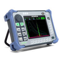
Olympus EPOCH 650 User Manual (362 pages)
Ultrasonic Flaw Detector
Brand:
Olympus
| Category:
Measuring Instruments
| Size: 5.38 MB
Table of Contents
Table of Contents
3
List of Abbreviations
11
DMTA-10055-01EN, Rev. A, February
12
Figure I-1 Labels Location
13
Labels and Symbols
13
Figure I-2 Location of the Serial Number
14
Figure I-3 Warning Symbol
14
Table 1 Rating Label and Regulatory Screen Content
15
Table 2 Serial Number Label Content
16
Important Information - Please Read before Use
17
Intended Use
17
Instruction Manual
17
Instrument Compatibility
18
Repair and Modification
18
Safety Symbols
19
Safety Signal Words
19
Note Signal Words
20
Safety
21
Warnings
21
Battery Precautions
22
Equipment Disposal
23
CE (European Community)
23
WEEE Directive
23
China Rohs
24
Korea Communications Commission (KCC)
24
EMC Directive Compliance
24
FCC (USA) Compliance
24
ICES-001 (Canada) Compliance
25
Warranty Information
25
Technical Support
26
Introduction
27
Package Content
28
Figure I-4 Transport Case Contents
29
DMTA-10055-01EN, Rev. A, February
29
1 Hardware Overview
31
Figure 1-1 EPOCH 650 Front View
31
Figure 1-2 EPOCH 650 Rear View
32
Front Panel
32
Figure 1-3 the EPOCH 650 - Adjustment Knob Configuration
33
Figure 1-4 the EPOCH 650 - Navigation Pad Configuration
33
Adjustment Knob Configuration
34
Figure 1-5 Coarse (Left) and Fine (Right) Adjustment Selection
34
Figure 1-6 the EPOCH 650 - Adjustment Knob Configuration
35
Figure 1-7 Knob Configuration (English and International Versions)
36
Figure 1-8 Knob Configuration (Chinese and Japanese Versions)
37
Navigation Pad Configuration
37
Figure 1-9 the EPOCH 650 - Navigation Pad Configuration
38
Figure 1-10 Pad Configuration (English and International Versions)
39
Direct-Access Keys
40
Figure 1-11 Pad Configuration (Chinese and Japanese Versions)
40
Table 3 English Direct-Access Key Descriptions
41
Function and Parameter Keys
42
Figure 1-12 Function and Parameter Keys
43
Alarm Indicators
44
Figure 1-13 Menu System Software Buttons
44
Figure 1-14 AC Charger/Adaptor Power Indicator
44
Power Indicator
44
Connectors
45
Figure 1-15 Alarm Indicators
45
Transducer Connectors
45
Digital out Connector
46
Figure 1-16 Location of the Transducer Connectors
46
Alarm Output Connector Pins
47
Encoder Input Pins
47
Serial Communication Pins
47
Trigger Input and Output Pins
48
VGA out Connector
48
Figure 1-17 the RS-232/Alarms and VGA out Connectors
49
USB Client Port and Microsd Card Slot
49
Figure 1-18 the Connectors Behind the Protective Cover
50
USB Client Port
50
Figure 1-19 Installing the Microsd Card
51
Microsd Card Slot
51
Battery Compartment
52
Figure 1-20 the Battery Compartment
52
Figure 1-21 Instrument Resting on Stand
53
Instrument Stand
53
2 Powering the EPOCH 650
55
Figure 2-1 Location of the EPOCH 650 Power Key and Indicator
55
Lithium-Ion Battery
56
AC Charger/Adaptor
57
Figure 2-2 Connecting the Charger/Adaptor
58
Figure 2-3 Connecting the DC Power Plug
58
Figure 2-4 Front Panel AC Charger/Adaptor Power Indicator
59
Power Status Indicators
59
Standalone Battery Charger
59
Table 4 EPOCH 650 Power Status Indicators
59
3 Software Overview
61
Figure 3-1 Software Main Display Elements
61
Choosing a Function Menu Item
62
Figure 3-2 the Menu Groups and Their Level Numbers
62
Figure 3-3 F1 Key Selecting the Basic Function
62
Figure 3-4 the Focus Is on the Selected Parameter (Green)
63
Parameter Selection
63
Convention for Identifying Menu Items and Parameters
64
Figure 3-5 P3 Key Selecting the Range Parameter
64
Parameter Adjustment
64
Escape Key
65
Lock Key
65
AUTO XX% Feature
66
Figure 3-6 Adjustment Knob Configuration - Lock Key
66
Figure 3-7 the AUTO XX% Feature: Inactive (Left) and Active (Right)
66
Submenus
66
Pulser and Receiver Settings
67
Reference Gain
67
Sensitivity
67
Figure 3-8 the Reference and Scanning Gains
68
Pulser
68
Receiver
68
DMTA-10055-01EN, Rev. A, February
69
Table 5 Filter Cutoffs
69
3.10 Gates
70
Figure 3-9 the Gate 1 Start Position Adjustment
70
Quickly Adjusting Basic Gate Parameters
70
Gate 1 and Gate 2
71
Gate Setup
71
Figure 3-10 Trigger in Edge and Peak Modes
72
Figure 3-11 Trigger in 1Stpeak, and J-Flank Modes
73
Figure 3-12 Gate 1 and Gate 2 Alarm Indicator Lights
73
Gate Alarm Indications
73
3.11 Calibration
74
Measurement Calibration
74
Figure 3-13 the Auto Cal Menu
75
Figure 3-14 the Cal-Zero Value
76
Figure 3-15 the Gate 1 Start
77
Figure 3-16 the Velocity Cal Value
78
Figure 3-17 the Range Value
78
Angle Beam Calibration
79
Figure 3-18 Reference Gain Setting
79
3.12 Data Logger
80
Calibration Files
80
Figure 3-19 the Create Screen with Virtual Keypad
81
Figure 3-20 the Save Dialog Box
82
Resetting the Instrument
82
Figure 3-21 the Resets Page
83
4 Software Interface
85
Figure 4-1 Software Main Display Elements
85
Button Types
86
Figure 4-2 Software Display Elements in Full Screen Mode
86
Table 6 Button Types
86
Figure 4-3 File Identifier Bar with ID Example
87
Figure 4-4 Message Bar with a Message Example
87
File Identifier and Message Bars
87
Direct-Access Parameters
88
Figure 4-5 Example of the Gain, Range, and Delay Direct-Access Parameters
88
Figure 4-6 Direct Access Preset Values
89
Figure 4-7 Example of Measurement Reading Boxes with Their Icons
89
Measurement Reading Boxes
89
Figure 4-8 Example of an A-Scan Waveform with Gates
90
Flags
90
Live-Scan Area
90
Figure 4-9 the Area Displaying Flags
91
Table 7 Flag Description
91
Menu Contents
94
Figure 4-10 Standard Menu Groups
95
Table 8 Content of the First Menu Group
95
Table 10 Content of the Third Menu Group
96
Table 11 Content of the Fourth Menu Group
96
Table 9 Content of the Second Menu Group
96
Table 12 Content of the Fifth Menu Group
97
Setup
98
Entering an Alphanumeric Value Using the Virtual Keyboard
99
Figure 4-11 the Display Setup Page and Its Elements
99
Figure 4-12 the Edit Page with Its Virtual Keyboard
100
Display Setup Page
101
Figure 4-13 the Display Setup Page
101
Figure 4-14 the Reading Setup Page
103
Grid Setup Page
103
Reading Setup Page
103
Figure 4-15 Example of Measurement Reading Boxes with Icons
104
Table 13 Available Measurement Readings
105
General Setup Page
107
Figure 4-16 the General Setup Page
108
About Page
110
Figure 4-17 the Status Setup Page
110
Clock Setup Page
111
Figure 4-18 the Clock Setup Page
111
Misc Setup Page
112
Software Options Setup Page
112
Editable Parameters Page
114
Figure 4-19 Misc Setup Page
114
Figure 4-20 Editable Parameters Setup Page
115
Analog Output Setup Page
116
5 Adjusting the Pulser/Receiver
117
Adjusting the System Sensitivity (Gain)
117
Using the AUTO XX% Feature
117
Setting Reference Gain and Scanning Gain
118
Pulser Adjustments
119
Pulse Repetition Frequency (PRF)
119
Pulse Energy (Voltage)
120
Damping
121
DMTA-10055-01EN, Rev. A, February
121
Test Mode
121
Pulser Type
122
Pulser Frequency Selection (Pulse Width)
123
Receiver Adjustments
123
Digital Receiver Filters
123
Table 14 Advanced Filters
124
Waveform Rectification
125
6 Managing Special Waveform Functions
127
Reject
127
Peak Memory
128
Figure 6-1 Horizontal Line Indicating the Reject Level
128
Figure 6-2 Peak Memory Signal Envelope Example
129
Peak Hold
130
Freeze
130
Grid Modes
131
Figure 6-3 Selecting the X-Axis Grid Mode
132
Figure 6-4 the X-Axis Grid Modes
133
Baseline Break
134
Figure 6-5 the Y-Axis Grid Modes: 100 % (Left), 110 % (Right)
134
7 Gates
135
Measurement Gates 1 and 2
135
Figure 7-1 Gate 1 and Gate 2 (with Echo-To-Echo Turned On)
135
Figure 7-2 the Gate 1 Menu
136
Quickly Adjusting Basic Gate Parameters
137
Figure 7-3 the Direct-Access Gate Parameter Box
137
Gate Measurement Modes
138
Figure 7-4 the Gate Setup Menu
139
Figure 7-5 Trigger Indicator on Gate in Edge and Peak Modes
140
Figure 7-6 Trigger Indicator on Gate in 1Stpeak, and J-Flank Modes
141
Viewing Measurement Readings
142
Gate Tracking and Echo-To-Echo Measurements
142
Figure 7-7 Echo-To-Echo Measurement Example
143
Operating in Time-Of-Flight Mode
144
Zooming on a Gate
144
Gate Alarms
145
Threshold Alarms
145
Figure 7-8 Gate Tick Marks Indicating Alarm Threshold Type
146
Minimum Depth Alarm
146
Minimum Depth Alarm with a Single Gate
146
Figure 7-9 Minimum Depth Alarm Marker
147
Minimum Depth Alarm with Gate Tracking
147
8 Programmable Inputs and Outputs
149
Alarm Outputs
149
Serial/Usb Command Protocol
149
Trigger Inputs and Outputs
150
Encoder Inputs
151
Analog Output
151
Figure 8-1 the A-Out Setup Page
153
9 Calibration
155
Basic Setup
155
Calibration Modes
156
Angle Beam Modes
157
Straight Beam Modes
157
Calibrating with a Straight Beam Transducer
158
DMTA-10055-01EN, Rev. A, February
158
Figure 9-1 Example of a Gated Signal for Zero Calibration
159
Figure 9-2 Entering the Zero Cal Thickness Value
160
Figure 9-3 Example of a Gated Signal for Velocity Calibration
161
Calibrating with a Delay Line Transducer
162
Figure 9-4 Entering the Velocity Cal Thickness Value
162
Figure 9-5 Adjusting Zero Offset for the First Delay Line Echo
164
Figure 9-6 Example of a Gated Signal for Zero Calibration
165
Figure 9-7 Entering the Zero Cal Thickness Value
166
Figure 9-8 Example of a Gated Signal for Velocity Calibration
167
Calibrating on a Single Test Block of Known Thickness
168
Calibrating with a Dual Element Transducer
168
Figure 9-9 Entering the Velocity Cal Thickness Value
168
Figure 9-10 Example of a Gated Signal for Zero Calibration
170
Figure 9-11 Entering the Zero Cal Thickness Value
171
Figure 9-12 Example of a Gated Signal for Velocity Calibration
172
Calibrating in Echo-To-Echo Mode
173
Figure 9-13 Entering the Velocity Cal Thickness Value
173
Figure 9-14 Example of Gated Signals for Velocity Calibration
175
Figure 9-15 Entering the Velocity Cal Thickness Value
176
Calibrating to Known Sound Path Values with an Angle Beam Transducer
177
Locating the Beam Index Point
177
Figure 9-16 IIW Block with Probe at 0 Mark
178
Figure 9-17 Using the Peak Memory Feature to Find the BIP
179
Verifying the Refracted Angle
179
Figure 9-18 the IIW Block with Probe at the 45° Mark
180
Calibrating for Distance
181
Figure 9-19 Verifying the Refracted Angle
181
Figure 9-20 Example of a Gated Signal for Zero Calibration
182
Figure 9-21 Entering the Zero Cal Thickness Value
183
Figure 9-22 Example of a Gated Signal for Velocity Calibration
184
Calibrating for Sensitivity
185
Figure 9-23 Entering the Velocity Cal Thickness Value
185
Figure 9-24 the IIW Block with Probe Facing Sensitivity Hole
186
Calibrating to Known Depth Values with an Angle Beam Transducer
187
Figure 9-25 Setting the Reference Gain
187
Figure 9-26 Example of a Gated Signal for Zero Calibration
189
Figure 9-27 Entering the Zero Cal Thickness Value
190
Figure 9-28 Example of a Gated Signal for Velocity Calibration
191
9.10 Curved Surface Correction
192
Figure 9-29 Entering the Velocity Cal Thickness Value
192
9.11 Common Angle Beam Calibration Block Diagrams
193
Figure 9-30 the ASTM E164 IIW Type Calibration Block (P/N: TB7541-1)
193
Figure 9-31 the IIW Type 2 Reference Block (P/N: TB5939-1)
194
Figure 9-32 the Distance and Sensitivity Calibration (DSC) Test Block (P/N: TB7549-1)
195
Figure 9-33 the ASTM E164 IIW Type Metric Calibration Block (P/N: TB1054-2)
196
Figure 9-34 the ISO 7963 MAB Calibration Block (P/N: TB1065-1)
197
Figure 9-35 the Navships Cylindrical Reflector Block (P/N: TB7567-1)
197
Figure 9-36 the 5-Step Precision Thickness Calibration Block (P/N: 2214E)
198
10 Data Logger
199
10.1 Data File Types
200
Advanced File Types
200
Calibration File Type
200
Incremental File Type
200
2-D Epri
201
2-D Matrix Grid
201
2-D Matrix Grid with Custom Point
201
Sequential
201
Sequential with Custom Points
201
Boiler
202
10.2 Data Logger Storage Capacity
202
10.3 Saving Data to Files
202
10.4 Data Logger Menus
203
File Menu
203
Create
204
Figure 10-1 the File Menu Parameters
204
Figure 10-2 the Create Setup Page
205
Figure 10-3 File Name Edit
206
Figure 10-4 Creating Advanced File Type
207
Figure 10-5 Advanced (Create
208
Open
209
Figure 10-6 the Open Page
210
Figure 10-7 ID of Open File in the Live Screen
210
Figure 10-8 the Details Page
211
Figure 10-9 Viewing File Content (Waveform)
212
Figure 10-10 Viewing File Content (Setup)
213
Figure 10-11 Select ID Page
214
Figure 10-12 File Measurement Summary
215
Figure 10-13 the Recall Setup Menu
216
Quick Recall
216
Figure 10-14 Memo Setup Page
217
Memo
217
Figure 10-15 Memo Dictionary Page
218
Figure 10-16 Populated Memo Setup Page
219
Last ID and Select ID
219
Figure 10-17 the Select ID Menu
220
Manage Menu
220
Figure 10-18 the Manage Menu Parameters
221
Reset
221
Export
222
Figure 10-19 Export Setup Page
223
Import
223
Figure 10-20 Import Page
224
Edit
225
Figure 10-21 Import (Memo) Page
225
Copy
226
Figure 10-22 the Edit Setup Menu
226
DMTA-10055-01EN, Rev. A, February
227
Figure 10-23 the Copy Setup Menu
227
Figure 10-24 the Delete Setup Menu
228
Import Memo
228
Grid View
229
Using the Grid
230
Figure 10-25 Grid Controls in the Live Screen
231
Figure 10-26 Grid Controls in Contents Screen
232
Screen Capture
233
11 Software Features and Options
237
Figure 11-1 the Option Key Entry Dialog Box
238
Dynamic DAC/TCG
238
Feature Activation and Reference Correct
239
Figure 11-2 the DAC/TCG Setup Page
240
Figure 11-3 First DAC Setup Step
241
Standard/Asme III DAC/TCG
241
Figure 11-4 DAC Setup One Point
242
Figure 11-5 Partial DAC Curve with each Echo Set to 80 % FSH
243
Figure 11-6 the Completed DAC Curve
244
Figure 11-7 Completed DAC Curves in TCG View Mode
245
Figure 11-8 a Small Range DAC
246
Gain Adjustment Options
246
Figure 11-9 Standard DAC with 3 Db Scanning Gain
247
Curve Adjustment Gain (DAC Gain or TCG Gain)
248
Figure 11-10 DAC with 3 Db Scan Gain - Reference Correction Active
248
Figure 11-11 DAC Curves with Adjusted Gain
249
Transfer Correction
249
Jis Dac
250
Figure 11-12 Custom DAC Setup
251
Dgs/Avg
252
Figure 11-13 Completed Custom DAC
252
Option Activation and Setup
253
Figure 11-14 DGS/AVG Setup Page
254
Figure 11-15 Reference-Reflector before Capture
257
Curve Adjustment Options
258
Figure 11-16 DGS/AVG Curves on Screen
258
DGS/AVG Curve Gain
259
Figure 11-17 Gain Curve Adjusted DGS
260
Registration Level Adjustment
260
Relative Attenuation Measurement
261
Activating the AWS D1.1 Software Option
262
Adjusting the AWS Reference Level
263
Figure 11-18 AWS Setup Page
263
Figure 11-19 Reference B Value before Storage
264
Storing the Gated Reflector
264
Figure 11-20 Active AWS with D Rating
265
Scanning Gain
265
Calculating a and C Values
266
Figure 11-21 Completed API 5UE Sizing
268
Option Activation and Setup
268
Figure 11-22 Waveform Averaging Option Setup
269
Envelope Mode
270
Crack Sizing
271
Figure 11-23 Calibration Data in Collect Mode
271
Figure 11-24 the Inspect Mode
272
Manual Mode
273
DMTA-10055-01EN, Rev. A, February
274
Figure 11-25 Storing the a Max Point
274
Figure 11-26 Storing the T 1 Point
275
Crack Sizing
276
Figure 11-27 Storing the T 2 Point
276
Waveform Averaging
277
Figure 11-28 Waveform Averaging Option Setup
278
Figure 11-29 the Waveform Averaging Screen
279
Back Wall Echo Attenuator
280
Figure 11-30 Update Rate Less than 60 Hz
280
Figure 11-31 Activating the BEA
281
Figure 11-32 Adjusting Back Wall Gain
282
Interface Gate
283
Figure 11-33 Setting the Material Velocity
284
Figure 11-34 Setting the Gate Interface Run Mode
285
Figure 11-35 Interface Gate and TCG
286
Interface Gate Compatibility
286
Gate Measurements and Alarms
287
Corrosion Module Screen
288
Figure 11-36 Corrosion Module Screen
289
Corrosion Module Activation and Setup
290
Figure 11-37 Corrosion Module Grid View
290
Figure 11-38 Corrosion Module Transducer Setup Menu
291
Basic Measurement Adjustments
292
Figure 11-39 Incorrectly Triggered Measurement
293
Manual Gain Adjustment
293
Figure 11-40 Corrosion Module AGC Set to off
294
Calibration for Additional Accuracy
295
Figure 11-41 Adjusting the Corrosion Module Gain Value
295
Figure 11-42 Corrosion Module Echo Measurement
296
B-Scan
297
Figure 11-43 Echo Measurement Error
297
Activating the B-Scan
298
B-Scan Setup
299
Figure 11-44 B-Scan Menu Item
299
B-Scan Acquisition and Control
301
Figure 11-45 B-Scan Setup Page
301
Figure 11-46 B-Scan Position Indicator
302
Viewing the B-Scan in the Data Logger
302
Figure 11-47 B-Scan Display in the Data Logger
303
Template Storage
304
Figure 11-48 Template Setup Page
305
Figure 11-49 -A- Indicates an Active Template
306
Figure 11-50 Stored Template Display in Live Screen
307
Figure 11-51 Template Setup Page
308
12 Maintenance and Troubleshooting
309
Replacing the Battery
309
Figure 12-1 Removing the Lithium-Ion Battery
310
Instrument Cleaning
310
Troubleshooting
311
Table 15 General Specifications
313
Table 16 Environmental Ratings Specifications
314
Table 17 Pulser Specifications
315
Table 18 Receiver Specifications
315
Table 19 Calibration Specifications
315
Channel Specifications
315
Table 20 Gate Specifications
316
Table 21 Measurement Specifications
316
Table 22 Input/Output Specifications
317
Table 23 EPOCH 650 15-Pin Digital Port Output
317
Table 24 EPOCH 650 15-Pin VGA Port Output
318
DMTA-10055-01EN, Rev. A, February
318
Table 25 Ultrasonic Velocities in a Variety of Common Materials
319
Appendix A: Sound Velocities
319
Appendix B: Data File Types
321
Table 26 Example of Start ID# = ABC123
324
B.3 Advanced File Types
324
Table 28 Example of Starting ID# = XYZ1267
325
Table 27 Example of Start ID# = XY-GY
325
Figure 13-1 2-D Matrix Grid
326
B.3.2 2-D Matrix Grid
326
Figure 13-2 One Grid for 75 Identical Parts
327
Figure 13-3 Different Named Grid for each Part
328
Table 29 Example of 2-D Matrix Grid with Custom Point
329
B.3.3 2-D Epri
329
Table 30 Example of 3-D Grid
330
B.3.5 3-D Matrix Grid
330
Table 31 Example of a BOILER File
331
B.3.6 Boiler
331
Table 32 Glossary
333
Appendix C: Glossary
333
Table 33 EPOCH 650 Basic Kit (Spares Can be Purchased)
343
Appendix D: Parts List
343
Table 34 EPOCH 650 Software Options
344
Table 35 EPOCH 650 Optional Accessories
344
List of Figures
347
List of Tables
353
Index
355
DMTA-10055-01EN, Rev. A, February
356
Advertisement
Olympus EPOCH 650 Getting Started Manual (13 pages)
Ultrasonic Flaw Detector
Brand:
Olympus
| Category:
Security Sensors
| Size: 1.36 MB
Table of Contents
Contents of the Case
2
Charging the Lithium-Ion Battery
3
To Replace the Battery
4
Software User Interface
6
Menu Groups
7
Battery Precautions
9
Electrical Warnings
9
Equipment Disposal
9
Advertisement
Related Products
Olympus Element
Olympus Panametrics Epoch 4 Plus
Olympus EPOCH 600
Olympus EPOCH 1000 Series
Olympus E-PL1
Olympus E-PL5
Olympus E-P5
Olympus E-PL6
Olympus E-P5 1442 Kit Silver
Olympus E-PM2 1442
Olympus Categories
Digital Camera
Voice Recorder
Microscope
Camera Accessories
Camera Lens
More Olympus Manuals
Login
Sign In
OR
Sign in with Facebook
Sign in with Google
Upload manual
Upload from disk
Upload from URL