Sign In
Upload
Manuals
Brands
Norton Manuals
Motorcycle
Commando 850
Norton Commando 850 Manuals
Manuals and User Guides for Norton Commando 850. We have
1
Norton Commando 850 manual available for free PDF download: Workshop Manual
Norton Commando 850 Workshop Manual (173 pages)
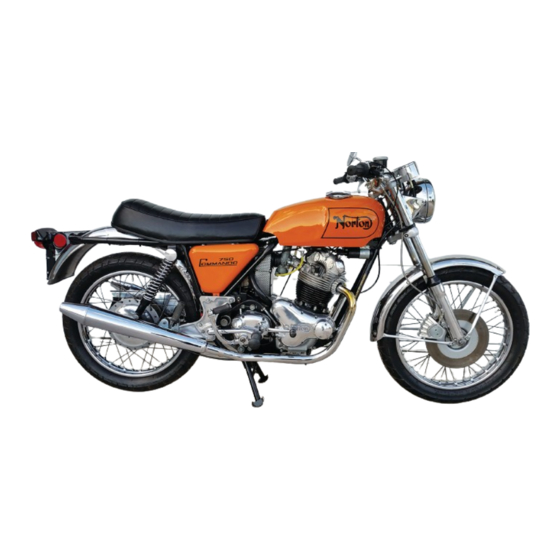
norton commando 850
Brand:
Norton
| Category:
Motorcycle
| Size: 17.1 MB
Table of Contents
Contents
4
Technical Data
10
Technical Data: Frame, Engine Mountings and Rear Suspension Units
11
Technical Data: Speedometer Gearing
11
Technical Data: Wheels and Brakes
12
Technical Data: Electrical
13
Technical Data: Engine
14
Technical Data: Torque Settings
18
Technical Data: Gearbox
19
Technical Data: Capacities
20
Technical Data: Miscellaneous Data
21
Technical Data: Special Workshop Tools
22
Conversion Tables
24
U.N.E.F., U.N.F., U.N.C. Threads
25
B.A., B.S.W., B.S.F. Threads
25
Wire Gauges Conversion Table
26
Drill Sizes Conversion Table
26
Pints to Liters Conversion Table
27
Gallons to Liters Conversion Table
27
Miles to Kilometers Conversion Table
27
Miles Per Gallon to Liters Per 100 Kilometers
27
Pounds Per Square Inch to Kilograms Per Square Centimetre Conversion Table
28
Pounds to Kilograms Conversion Table
28
Foot Pounds to Kilogrameters Conversion Table
28
Millimeters to Inches Conversion Table
29
Inches to Millimeters (Decimals Of) Conversion Table
30
Fractions to Decimals - Decimals of Inch to Millimetre Conversion Table
30
Engine and Primary Transmission
31
Engine and Primary Transmission: Exploded View
32
Engine/Primary Drive
33
Removing Cylinder Head
33
Tightening Sequence
33
Removal of Rockers
34
Valve Removal and Reassembly
35
Rocker Thrust Washers and Securing Plates
35
Extracting Rocker Spindles Using Slide Hammer 064298
35
Decarbonising
36
Valve Guide Renewal
36
Using Valve Guide Tool 063964 to Remove a Valve Guide
37
Reseating the Valves
38
Grinding-In the Valves
38
Aligning Rocker Spindle
38
Refitting Rockers
39
Refitting Cylinder Head
39
Guiding Pushrods into Engagement with the Rockers
39
Rocker Clearances
40
Removing Cylinder and Pistons
41
Checking Valve Clearances
41
Support Connecting Rods to Prevent Damage against Crankcases
41
Cylinder Reboring and Oversize Pistons
42
Supporting Piston Body Whilst Pushing out Gudgeon Pin
42
Removing Primary Chaincase
43
Dismantling Primary Transmission and Clutch
43
Removing Rotor Nut Whilist Applying Rear Brake to Prevent Movement
43
Diaphragm Spring Compressor Tool 060999 in Use
44
Removing Crankcase Assembly from Frame
45
Removing Engine Sprocket Clutch and Primary Chain as a Set
45
Using a Screwdriver Blade to Peel Circlip Away from Housing
45
Use of Engine Sprocket Puller 064297
45
Dismantling the Crankcases
46
Removal of the Crankcase Assembly from Mounting Plates
46
Showing Crankcases Supported by a Bar to Remove Sump Filter
46
Showing Crankcases Mounted in a Plain Jaw Vice for Ease of Handling
46
Removing Contact Breaker Cam Using Slide Hammer 064298
47
Using a Spanner to Turn the Oil Pump Drive Wheel Nut and Remove the Pump
47
Preventing Flywheel Turning by Use of a Bar Lodged in a Flywheel Balance Hole
48
Extracting Crankshaft Pinion Tool ET 2003
48
Parting the Crankcase Using a Wood Block against the Inner Drive Side
49
Crankcase Overhaul
50
Removing Connecting Rods
50
Showing Suitable Tube to Abutt to Crankshaft Shoulder yet Pass through Crankcase
50
Supporting the Crankcase Shoulder on a Tube Whilist Separating the Crankcase from the Crankshaft
50
Dismantling the Cranckshaft
51
Cranckshaft Inspection and Regrinding
51
Engine Lubrication System
51
Removing Roller Bearing Inner Race Using Extractor 063970
51
Engine Lubrication System 850 Models
53
Oil Pressure Relief Valve
54
Crankcase Breather
54
Servicing the Oil Pump
54
Oil Pump
54
Timing Cover
55
Contact Breaker Seal, Crankshaft Seal
55
Showing Blanking Plug in Position in Timing Cover
55
Positions and Lengths of Odd Timing Cover Screws
55
Re-Assembly of the Crankshaft
56
Re-Assembling Connecting Rods to Crankshaft
56
Showing Crankcheek to Flywheel Securing Hardware
56
Connecting Rods Showing both Sides of Big and Eye and Bearing Shell Tab Locations
56
Re-Assembling Crankshaft to Crankcases
57
Pushing Timing Side Crankcase over Crankshaft
57
Mating Crankcases
57
Assembling Right (Timing Side) of Engine
58
Assembly of Timing Chain and Sprockets
58
Refitting the Timing Cover
59
Chain Tensioner Showing Thin Inner Plate Long End Downwards
59
Re-Assembly of Crankcase Assembly to Frame
60
Inserting Front Left Gaiter Mounting Cap Group
60
Lifting Front Mounting into Position Using Bottom Bolt as Pivot
60
Refitting Pistons and Cylinder
61
Priming Crankshaft with Oil
61
Assembling Primary Transmission
62
Fitting Cylinder over Pistons
62
850 Cylinder Base Securing Torque
62
Using Grip Wrench to Squeeze over Tab Washers at Inner Chaincase
63
Winding Diaphragm Spring Circlip into Position
63
Clutch Operating Lever in Correct Position
64
Clutch Operating Lever in Wrong Position Where Lever Has Dropped down
64
Clutch Operating Mechanism
65
Clutch Plates
65
Clutch Adjustment
65
Plate Inspection
65
Tachometer Drive
66
Removing and Refitting Engine Complete
66
Ignition Timing
66
Ignition Timing Basic Procedure Prior to Checking
67
Ignition Timing Procedure - Engine Static
67
Timing Plate Visible after Removal of Inspection Cap from Chaincase
67
Ignition Timing Procedure - Engine Running
68
Auto Advance Unit
69
Contact Breaker Assembly
69
Adjusting Contact Breaker Points Gap
69
C50 Lucas Contact Breaker
69
Maintenance of the Contact Breaker
70
Primary Chain Adjustment
70
Chain Serviceability
70
Rear Chain Adjustment
71
Gearbox
72
Gearbox Description
73
Gearbox Dismantling
73
Removing Gearbox Outer Cover
73
Removing Gearbox Inner Cover
73
Dismantling Gear Cluster and Cam Plate
74
Inspection of Gearbox Parts
74
Removal of Gearbox Complete
75
Countershaft (Gearbox Final Drive) Sprocket
75
Changing the Countershaft Sprocket
75
Refitting Gear Cluster and Selectors
76
Mainshaft and Layshaft Fitted to Gearbox Shell
76
Location of Camplate to Index Plunger
76
Refitting Gearbox Inner Cover
77
Gear Layout
77
Showing Kickshaft Pawl Stop on Inner Cover
77
Dismantling and Re-Assembling Gearbox Outer Cover
78
Kickstart Spring Located
78
Order of Assembly of Clutch Withdrawal Lever
78
Refitting the Gearbox Outer Cover
79
Pawl Carrier, Spring and Pichet Plate Assembled
79
Carburetor
80
Carburetor Removal
81
Amal Concentric Float Carburetor
81
Carburetor Dismantling
82
Carburetor Reassembly
82
Examination of Carburetor Parts
82
Fuel Taps
83
Carburetor Adjustment
83
Twin Carburetor Adjustment
84
Adjustment for Altitude
84
Air Filter
85
Removing and Refitting the Elements
85
Cleaning the Air Filter Element
85
Removing Air Filter and Gauze Band
85
Frame and Ancillaries
86
Removal of Power Unit
87
Removing Oil Junction Block Securing Bolt
87
Lifting out Power Unit to Right Side
88
Isolastic Engine Mountings
89
Commando Parted to Show Isolastic Mounting Points
89
Frame Checking Charts
90
Frame Checking Dimensions
91
Refitting Power Unit
91
Gaiter/Collar Group Ready to Fit
91
Coil Cluster from Rear Beneath
92
Swinging Arm Offered into Position with End Cap Held in Place with Grease
93
Aligning Swinging Arm Spindle with Swinging Arm Bore
94
Spindle Lock Bolt Fitted
94
Removing and Refitting Suspension Units
95
Rear Suspension Units (Girling)
95
Changing the Spring
95
Rebushing the Swinging Fork
95
Removing and Replacing Fuel Tank
96
Swinging Arm Bushes Showing Order of Assembly
96
Removing and Refitting Oil Tank
98
L.H. Accessory and R.H. Covers
99
Shimming Engine Mountings
99
Checking Rear Shimming, Front Shimming
99
Adjusting Front Shimming
99
Adjusting Rear Shimming
101
Holding Front Mounting in a Vice for Checking
101
Using Service Tool 063971 to Insert Front Isolatic Rubber Bushes
102
Renewal of Rubbers and Buffers
103
Renewing Isolastic Mounting Rubbers
103
Isolastic Mountings Exploded View
103
Rear Fender
104
Exhaust System Removing and Refitting
105
750 Low Lever Exhaust Systems
106
S Type Exhaust
107
850 Exhaust Systems
108
Front Forks/Steering
109
Fork at Rest, Compressing, Extending and Almost Fully Extended
110
Front Fork Description
112
Fork at Rest
112
How Fork Works
112
Fork Extending , Fork Compresses
112
Removal of Front Forks
113
Hydraulic System Removed Complete
113
Shocking Main Tubes Free of Upper Yoke
114
Dismantling Fork Leg
115
Front Fork Exploded View
115
Reassembling Fork Leg
116
Hydraulic System Fitting to Fork Leg
116
Releasing Damper Rod from Fork Top Bolts
116
Renewing Steering Head Bearings
117
Steering Head Adjustment
117
Refitting Font Forks
118
Showing Stem Nut Tab Washer Locked to Nut
119
Brakes, Wheels and Tires
120
Removing Rear Wheel
121
Refitting of Rear Wheel
122
Complete Rear Wheel Removal
122
Paddles and Shock Absorbing Pads
122
Rear Hub Dismantling
123
1970 Type Rear Wheel Exploded
123
1971 Onwards Rear Wheel Exploded
124
Rear Hub Reassembly
125
Removing and Refitting Front Wheel
126
Disk Brake Front Wheel Removal
126
Dismantling Front Hub, Disc Type
127
Guiding Brake Disc between Brake Pads
127
Removing and Refitting Front Wheel (Drum Type Brake)
128
Drum Front Brake External Features
128
Front Wheel Bearing Overhaul (Drum Brake)
129
Front Brake Adjustment (Drum Brake)
129
Twin Leading Shoe Brake Plate Showing Link Rod
129
Front Brake (Disc Type)
130
Rear Brake Adjustment
130
Overhauling Drum Brakes
130
Setting the Link Rod
130
Rear Brake Dismantling
131
Rear Brake Reassembly
131
Twin Leading Shoe Brake
131
Front Brake
131
Front Brake with High Performance Modification
132
Twin Leading Shoe Brake with High Performance Modification
132
Norton Lockheed Hydraulically Operated Disc Brake
133
Caliper Friction Pad Removal
133
Exploded View of Caliper Group
133
Caliper Overhaul
134
Caliper Component Inspection
134
Caliper Re-Assembly
135
Master Cylinder Overhaul
136
Master Cylinder Exploded View
136
Master Cylinder Removal
137
Master Cylinder Dismantling
137
Inspection of Master Cylinder and Components
137
Master Cylinder Reassembly
137
Tires
139
Master Cylinder Refitting
139
Bleeding the Hydraulic Brake System
139
Removing Front Tire
140
Refitting Front Tire
141
Removing Rear Tire
141
Refitting Rear Tire
142
First Bead Levered into the Rim
142
Careful Levering of Second Bead over Wheel Rim
142
Lifting Cover and Engaging Security Bolt to Rim
143
Pressing Security Bolt Back through Rim Whilist Levering Second Bead into Position
143
Electrical
144
Charging System
145
Alternator - Lucas Type RM21
145
Alternator Maintenance
145
Testing the Alternator in Situ
145
Rectifier Type 2DS 506
146
Testing the DC Input to Battery
146
Alternator Test
146
Rectifier Test Connections
146
Testing the Rectifier
147
Bench Testing the Rectifier
147
Zener Diode
148
Testing the Zener Diode
148
Battery Maintenance
148
Fuse, Ignition Switch, Master Switch
149
Warning Light Assimilator
149
High Rate Discharge Check
149
Testing Ignition System
150
Ignition Coils
150
Ignition and Lights
150
Ignition System Tests
150
Ignition Coils Lucas Type 17M6 1971 and Later Models/Type 17M12 Certain 1972 Models
151
Testing an Ignition Coil (17M6 and 17M12 Types)
151
Connect Breaker Assembly - Lucas Type 6CA
151
Ballast Resistors, Capacitor Pack Testing
151
Changing a Capacitor
152
Spark Plugs - Champion N7Y
152
Lighting System, Stop Switches
152
To Change the Headlamp and Pilot Bulbs, to Change the Tail/Stomplamp Bulb
152
Handlebar Switch Clusters
153
Power Take-Off Socket
153
Front Brake Stop Switch
153
Rear Stop Switch Adjustment
153
Flashing Direction Indicators
154
Alternator Horn Set Interpol Only Type HC3
154
Bulb Replacement, Checking for Faulty Operation
154
HC 3 Alternating Horn Control
154
Relays
155
Horn: Testing Procedure
155
Returning the 9H Alternating Horns
155
Contact Adjustment on Motorcycle
155
Electrolytic Capacitor 2MC
156
Horn Adjustment (Single Standard Horn)
156
Horn in Position
156
How to Make up a One Ohm Resistors
157
Pre-1971 Wiring Diagram
158
1971 Wiring Diagram
159
1972 And 1973 Wiring Diagram
160
Routine Maintenance
161
Routine Maintenance: Points
162
Breaking in
163
Lubrication Chart
164
Maintenance Table
165
Engine Oil Tank Level
166
Engine Oil Changing
166
Oil Tank Filter and Drain Plug
166
1970 S Roadster Oil Tank Unions
166
Crankcase Strainer and Drain Plug
167
Crankcase Gauze Strainer
167
Cartridge Type Oil Filter Location
167
Gearbox Oil Level, Gearbox Oil Changing
168
Primary Chaincase Oil Changing, Oil Level
168
Swinging Arm Pivot Lubrication
168
Front Fork Oil Changing
168
Checking Hydraulic Brake Fluid Level
169
Refilling Fork Leg with Cap Bolt Removed
169
Checking Master Cylinder Hydraulic Fluid Level
169
Checking Battery Electrolyte Level
170
Spark Plugs
170
Tire Pressures
170
Battery Electrolyte Level Mark
170
Adjusting Cam Timing Chain
171
Advertisement
Advertisement
Related Products
Norton Commando
Norton Commando 1969
Norton Commando 1970
Norton Commando 1973
Norton Combat 1973
Norton Clipper CP512-300i
Norton clipper CHW Series
Norton Clipper CTC1020XL
Norton clipper CR 11 B
Norton Clipper CB 311
Norton Categories
Saw
Door Opening System
Motorcycle
Drill
Trowels
More Norton Manuals
Login
Sign In
OR
Sign in with Facebook
Sign in with Google
Upload manual
Upload from disk
Upload from URL