Sign In
Upload
Manuals
Brands
Nortel Manuals
Network Router
Contivity 1100
Nortel Contivity 1100 VPN Router Manuals
Manuals and User Guides for Nortel Contivity 1100 VPN Router. We have
5
Nortel Contivity 1100 VPN Router manuals available for free PDF download: Install Manual, Configuration Manual, Installing, Manual, Connecting Manual
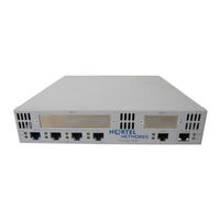
Nortel Contivity 1100 Install Manual (218 pages)
VPN Router
Brand:
Nortel
| Category:
Network Router
| Size: 2.89 MB
Table of Contents
Statement of Conditions
2
Table of Contents
7
Features
17
1000BASE-T (1000 GT) Ethernet Interface Card
17
New in this Release
17
Finding the Latest Updates on the Nortel Web Site
19
Getting Help from the Nortel Web Site
19
How to Get Help
19
Getting Help from a Specialist by Using an Express Routing Code
20
Getting Help over the Phone from a Nortel Solutions Center
20
Getting Help through a Nortel Distributor or Reseller
21
Preface
23
Acronyms
24
Before You Begin
24
Text Conventions
24
Related Publications
25
Printed Technical Manuals
27
Chapter 1 Nortel VPN Router 600 Option Installation
29
Shutting down the System to Add or Replace Hardware
30
Opening the Nortel VPN Router 600
30
Figure 1 Removing the Screws from the Bottom of the VPN Router 600
31
Figure 2 Removing the Chassis from the Steel Enclosure
32
Figure 3 Nortel VPN Router 600 System Board
33
Installing or Replacing an Option Card
34
Table 1 Supported Option Cards for the Nortel VPN Router 600
34
Figure 4 Removing the Blank Bracket from the Option Card Slot
36
Figure 5 Inserting the Option Card
37
Figure 6 Securing the Option Card in the Slot
38
Figure 7 Replacing the Chassis in the Steel Enclosure
38
Replacing a DIMM
39
Figure 8 Installing a DIMM
41
Chapter 2 Nortel VPN Router 1100 Option Installation
43
Table 2 Supported Option Cards for the Nortel VPN Router 1100
43
Installing or Replacing Option Cards
44
Figure 9 Nortel VPN Router 1100 System Board
45
Chapter 3 Nortel VPN Router 1700 and 1600 Option Installation
49
Shutting down the System to Add or Replace Hardware
50
Removing the Front Bezel and Top Cover
51
Figure 10 Removing the Front Bezel
51
Figure 11 Removing the Top Cover
53
Figure 12 Location of Option Card Slots and Dimms on the System Board
54
Attaching the Antistatic Wrist Strap
55
Figure 13 Location of the Grounding Jack for the Antistatic Wrist Strap
55
Installing or Replacing Option Cards
56
Table 3 Supported Option Cards for the Nortel VPN Router 1600 and 1700
56
Table 4 Supported Option Cards for the Nortel VPN Router 1600
58
Figure 14 Removing an Option Card or a Filler Panel
59
Figure 15 Installing an Option Card
60
Installing or Replacing Dimms
61
Figure 16 Replacing the Front Bezel
61
Figure 17 Installing or Removing a DIMM in a Nortel VPN Router 1700 or 1600
63
Chapter 4 Nortel VPN Router 1740 Option Installation
65
Chapter 7 Nortel VPN Router 2750 Option Installation. . . . . . . . . . . . . . . . . . . . . . . . 113
66
Shutting down the System to Add or Replace Hardware
66
Removing the Front Bezel and Top Cover
67
Figure 18 Removing the Front Bezel
67
Figure 19 Removing the Top Cover
68
Figure 20 Location of Option Card and DIMM Slots on the System Board
69
Attaching the Antistatic Wrist Strap
70
Figure 21 Location of the Grounding Jack for the Antistatic Wrist Strap
70
Installing or Replacing Option Cards
71
Table 5 Supported Option Cards for the Nortel VPN Router 1740
71
Installing or Replacing an Option Card
72
Installing the SSL VPN Module 1000 with Other Option Cards
72
Figure 22 Installing or Removing an Option Card
74
Figure 23 Replacing the Front Bezel
75
Installing or Replacing Dimms
76
Figure 24 Installing or Removing a DIMM
78
Chapter 5 Nortel VPN Router 1750 Option Installation
81
Shutting down the System to Add or Replace Hardware
82
Removing the Front Bezel and Top Cover
83
Figure 25 Removing the Front Bezel
83
Figure 26 Removing the Top Cover
85
Figure 27 Location of Option Card and DIMM Slots on the System Board
86
Attaching the Antistatic Wrist Strap
87
Figure 28 Location of the Grounding Jack for the Antistatic Wrist Strap
87
Installing or Replacing Option Cards
88
Table 6 Supported Option Cards for the Nortel VPN Router 1750
88
Installing the SSL VPN Module 1000 with Other Option Cards
89
Installing or Replacing an Option Card
90
Figure 29 Installing or Removing an Option Card
91
Installing or Replacing Dimms
92
Figure 30 Replacing the Front Bezel
92
Figure 31 Installing or Removing a DIMM
94
Chapter 6 Nortel VPN Router 2700 and 2600 Option Installation
97
Shutting down the System to Add or Replace Hardware
98
Figure 32 Removing the Front Bezel
99
Removing the Front Bezel and Top Cover
99
Figure 33 Removing the Top Cover
100
Figure 34 Location of Option Card Slots and Dimms on the System Board
101
Figure 35 Location of the Grounding Jack for the Antistatic Wrist Strap
102
Table 7 Supported Option Cards for the Nortel VPN Router 2600 and 2700
103
Table 8 Installing Other Option Cards with the SSL VPN Module 1000
104
Table 9 Supported Option Cards for the Nortel VPN Router 2600
105
Figure 36 Installing or Removing an Option Card
107
Figure 37 Replacing the Front Bezel
108
Table 10 Base and Maximum Memory for the Nortel VPN Router 2600 and 2700
109
Installing or Replacing Dimms
109
Figure 38 Installing or Removing a DIMM
111
Shutting down the System to Add or Replace Hardware
114
Figure 39 Removing the Front Bezel
115
Removing the Front Bezel and Top Cover
115
Figure 40 Removing the Top Cover
117
Figure 41 Location of Option Card and DIMM Slots on the System Board
118
Figure 42 Location of the Grounding Jack for the Antistatic Wrist Strap
119
Table 11 Supported Option Cards for the Nortel VPN Router 2750
120
Table 12 Installing Other Option Cards with the SSL VPN Module 1000
121
Installing or Replacing an Option Card
122
Figure 43 Installing or Removing an Option Card
123
Figure 44 Replacing the Front Bezel
124
Installing or Replacing Dimms
124
Figure 45 Installing or Removing a DIMM
126
Chapter 8 Nortel VPN Router 4600 Option Installation
129
Opening the VPN Router 4600
130
Figure 46 Removing the Nortel VPN Router 4600 Front Bezel
131
Figure 47 Nortel VPN Router 4600 Front Components
132
Nortel VPN Router 4600 System Board Layout
133
Figure 48 Sample Nortel VPN Router 4600 System Board
133
Installing or Replacing Option Cards
134
Table 13 Supported Option Cards for the Nortel VPN Router 4600
134
Figure 49 Installing Nortel VPN Router 4600 Option Cards
136
Installing or Replacing Dimms
137
Replacing a Power Supply
138
Figure 50 Installing Nortel VPN Router 4600 Dimms
138
Figure 51 Removing a Nortel VPN Router 4600 Power Supply
139
Replacing a Hard Disk Drive
140
Figure 52 Removing a Nortel VPN Router 4600 Hard Disk Drive
141
Chapter 9 Nortel VPN Router 5000 Option Installation
143
Preparing to Install Hardware Options
145
Option Cards, Dimms, and Fan Trays
145
Power Supplies
145
Hard Disk Drives
145
Shutting down the System to Add or Replace Hardware
146
Removing the Front Bezel and Top Cover
147
Figure 53 Removing the Front Bezel
148
Figure 54 Removing the Top Cover
149
Figure 55 Location of Option Cards, Dimms, and Fan Trays on the System Board
150
Attaching the Antistatic Wrist Strap
151
Figure 56 Location of the Grounding Jack for the Antistatic Wrist Strap
151
Figure 57 Nortel VPN Router 5000 Option Card Slots and Buses
152
Table 14 Supported Option Cards for the Nortel VPN Router 5000
153
Table 15 Optimal Placement of Option Cards in the Nortel VPN Router 5000
154
Figure 58 Flowchart for Option Card Installation in the Nortel VPN Router 5000
156
Installing or Replacing Option Cards
157
Support for 16 I/O Ports
157
Installing or Replacing an Option Card
157
Figure 59 Installing or Removing an Option Card
158
Figure 60 Replacing the Front Bezel
159
Installing or Replacing Dimms
160
Considerations for Installing Dimms
160
Figure 61 DIMM Memory Banks on the Nortel VPN Router 5000 Motherboard
160
Figure 62 DIMM Label: Example 1
161
Figure 63 DIMM Label: Example 2
161
Installing Dimms
162
Figure 64 Installing or Removing a DIMM
163
Replacing a Power Supply
164
Table 16 Model Number for each Chassis that Supports Either the 350-Watt or 500-Watt Power Supply
165
Figure 65 Location of the Nortel VPN Router 5000 and Nortel VPN Router 5000E Power Supplies (Rear of the Chassis)
166
Figure 66 Removing a Power Supply
167
Replacing a Hard Disk Drive
168
Figure 67 Inserting a Power Supply
168
Figure 68 Location of the Nortel VPN Router 5000 Hard Disk Drives
169
Figure 69 Removing a Hard Disk Drive
171
Figure 70 Inserting a Hard Disk Drive
172
Replacing a Fan Tray
173
Figure 71 Location of the Nortel VPN Router 5000 Fan Trays
173
Figure 72 Removing a Fan Tray
175
Figure 73 Installing a Fan Tray
176
Appendix A Technical Specifications
179
VPN Router Security Accelerator
181
Figure 74 VPN Router Security Accelerator Card
181
SSL VPN Module 1000
182
Figure 75 SSL VPN Module 1000
182
10/100BASE-TX Ethernet Interface Card
183
Figure 76 10/100BASE-TX Ethernet Interface Card (All Models Except VPN Router 1100)
183
Figure 77 10/100BASE-TX Ethernet Interface Card (for the VPN Router 1100 Only)
183
Table 17 10/100BASE-TX Ethernet Port Pinouts (All Models Except VPN Router 1100)
184
Table 18 10/100BASE-TX Ethernet Port Pinouts (VPN Router 1100 Only)
184
1000BASE-T (1000 GT) Ethernet Interface Card
185
Figure 78 1000BASE-T (1000 GT) Ethernet Interface Card (All Models Except VPN Router 1100)
186
Figure 79 VPN Router 1100 Full-Height 1000BASE-T (1000 GT)
186
Figure 80 VPN Router 1100 Half-Height 1000BASE-T (1000 GT)
187
Table 19 1000BASE-T (1000 GT) Ethernet Pinouts
187
1000BASE-T (1000 MT) Ethernet Interface Card
188
Figure 81 1000BASE-T (1000 MT) Ethernet Interface Card
188
1000BASE-SX Ethernet Interface Card
189
Figure 82 1000BASE-SX Ethernet Interface Card
189
Table 20 1000BASE-T Ethernet Port Pinouts
189
56/64K CSU/DSU WAN Interface Card
190
Figure 83 56/64K CSU/DSU WAN Interface Card
190
Figure 84 56/64K CSU/DSU WAN Interface Card (for the VPN Router 1100 Only)
190
Table 21 56/64K CSU/DSU Cable Pinouts for Crossover Connection
191
ADSL WAN Interface Card
192
Figure 85 ADSL WAN Interface Card
192
Table 22 56/64K CSU/DSU Cable Pinouts for Straight-Through Connection
192
Figure 86 ADSL WAN Interface Card (for the VPN Router 1100 Only)
193
Table 23 ADSL Annex a Cable Pinouts
193
Table 24 ADSL Annex B Cable Pinouts
193
ISDN BRI Interface Card
194
Figure 87 ISDN BRI S/T Interface Card or ISDN BRI U Interface Card
194
Figure 88 ISDN BRI S/T Interface Card (for the VPN Router 1100 Only)
194
Figure 89 ISDN BRI U Interface Card (for the VPN Router 1100 Only)
194
Table 25 ISDN BRI S/T Cable Pinouts
195
Table 26 ISDN BRI U Cable Pinouts
195
T1/E1 CSU/DSU WAN Interface Card
196
Figure 90 T1/E1 CSU/DSU WAN Interface Card (Half-Height Card)
196
Figure 91 T1/E1 CSU/DSU WAN Interface Card (Full-Height Card)
196
Figure 92 T1/E1 CSU/DSU WAN Interface Card (for the VPN Router 1100)
196
Table 27 T1/E1 CSU/DSU Cable Pinouts for Crossover Connection
197
Quad T1/E1 CSU/DSU WAN Interface Card
198
Figure 93 Quad T1/E1 CSU/DSU WAN Interface Card
198
Table 28 T1/E1 CSU/DSU Cable Pinouts for Straight-Through Connection
198
V.90 Modem Interface Card
199
Single V.35/X.21 WAN Interface Card
200
Figure 94 V.90 Modem Interface Card
200
Figure 95 V.90 Modem Interface Card (for the VPN Router 1100 Only)
200
Table 29 V.90 Modem Cable Pinouts
200
Figure 96 Single V.35/X.21 WAN Interface Card (Full-Height Card)
201
Figure 97 Single V.35/X.21 WAN Interface Card (Half-Height Card)
201
Figure 98 Single V.35/X.21 WAN Interface Card
201
Table 30 V.35 Cable Pinouts
202
Table 31 X.21 Cable Pinouts
203
Table 32 RS-232 DTE Cable Pinout
204
Table 33 RS-232 SDLC Cable Pinouts
205
Table 34 V.35 SDLC Cable Pinouts
207
HSSI WAN Interface Card
208
Figure 99 HSSI WAN Interface Card
208
Table 35 T3 Cable Pinouts
208
External Modem Adapter for the Nortel VPN Router 1010/1050/1100
210
Figure 100 Serial Cable Adapter for Connection to Modem (DB9-To-DB25)
210
Table 36 Null Modem Adapter Cable Pinouts
211
Index
213
Advertisement
Nortel Contivity 1100 Configuration Manual (178 pages)
VPN Router Basic Features
Brand:
Nortel
| Category:
Network Router
| Size: 1.9 MB
Table of Contents
Table of Contents
5
Before You Begin
15
Preface
15
Text Conventions
15
Acronyms
17
Related Publications
19
Hard-Copy Technical Manuals
20
How to Get Help
20
Finding the Latest Updates on the Nortel Web Site
20
Getting Help from the Nortel Web Site
20
Getting Help over the Phone from a Nortel Solutions Center
21
Getting Help from a Specialist by Using an Express Routing Code
21
Getting Help through a Nortel Distributor or Reseller
21
New in this Release
23
Features
23
Systemlog Lifetime or Disk Size Limit Usage Option
24
FTP Server Passive Mode Parameter
24
Source Ips Access Restriction to Management
24
SSH Server Configurations
24
Chapter 1 Overview
25
Network Deployment Alternatives
25
Virtual Private Networking
26
Figure 1 Typical PDN
26
Licensing Features
27
Figure 2 VPN Service Models
27
Command Line Interface
28
Federal Information Processing Standard (FIPS)
28
Chapter 2 Getting Started
29
IP Addressing
29
Figure 3 Sample IP Addressing Scheme
30
Table 1 Sample IP Addressing Associations
30
Management Virtual Address
31
Figure 4 MVA on Separate Subnet from Private Physical Interfaces
32
Figure 5 MVA on same Subnet as Private Physical Interface
33
Figure 6 MVA Managing from a Remote PC
33
Configuring MVA with the Serial Menu
34
Configuring Interfaces
36
Multinetting
38
Table 2 Services Supported on a Multinetted Interface
39
Changing the Management IP Address
41
Figure 7 Deployment Scenario
41
Restricting Source Ips Access to Management
44
Configuring ACL through the CLI
44
Accessing ACL through the GUI
45
Configuring the Serial Interface
45
Using Boot Modes
50
Managing through a Web Browser
50
Preparing for Configuration
52
Table 3 Web Interface Configuration Options
53
Table 4 Configuration Checklist
53
Welcome Window
56
Chapter 3 Setting up the Nortel VPN Router 1010, 1050, and 1100
59
Default Configuration
59
Figure 8 Default Configuration
60
Branch Office Quick Start Utility
61
Enterprise Environment
62
Service Provider Environment
63
Table 5 Subnet Assignments
63
Deployment Procedure
65
Table 6 BOQS Parameters
66
Branch Office Quick Start Template
67
Connecting for Internet Access
67
Before You Begin
67
Check that You Received the Following Items
67
Cable the VPN Router and Turn the Power on
68
Make Sure that Your Pcs Can Obtain IP Addresses Automatically
69
Test the VPN Router and Start the Quick-Start Tool
69
DHCP Instructions
70
Pppoe Instructions
70
Static IP Instructions
71
Compact Flash Disk
72
Chapter 4 Configuring User Tunnels
75
Figure 9 Tunnel Connection Configuration
75
Configuring Group Characteristics
78
Setting up User Tunnels
81
Configuring Inverse Split Tunneling
85
Figure 10 Inverse Split Tunneling
85
Figure 11 Inverse Split Tunneling
86
Inverse Split Tunneling
87
Using the 0.0.0.0/0 Subnet Wildcard
87
Configuring the Subnet Wildcard
87
Figure 12 Edit > Ipsec Page for Wildcard
88
Table 7 Split Tunneling Mode Options
88
Configuring Tunneling Modes Using the CLI
89
Chapter 5 Configuring the System
91
Configuring the System Identity
91
Setting up LAN Interfaces
93
Figure 13 LAN-To-Nortel VPN Router Connection
93
Edit LAN Interface Window
95
Multinetting
97
Figure 14 LAN > Interfaces Window
98
Figure 15 LAN Interfaces > Add IP Address Window
99
Configuring Multinetting Using the CLI
100
Adding an IP Address
100
Deleting an IP Address
100
Table 8 Adding/Deleting a Secondary Address
100
Table 9 Configuring OSPF over a Secondary Address
101
Table 10 Configuring RIP over a Secondary Address
102
Asynchronous Data over TCP
105
Figure 16 Asynchronous Data over TCP
105
Configuring Network Time Protocol (NTP)
106
Configuring System Settings
108
Using Proxy ARP
111
Using the SSH Server to Allow Secure Sessions
112
Using the GUI for SSH Server
112
Enabling the SSH Server
112
Figure 17 SSH Server
112
Configuring the SSH Server
113
Figure 18 Allowed Services Window
114
Using the CLI for SSH Server
115
Defining an SSH Server (CLI)
115
Enabling or Restarting the SSH Server
115
Displaying the Current Settings for the SSH Server
116
Disabling the SSH Server
116
Restricted Product - Export License Requirement
117
Chapter 6 Configuring Branch Office Tunnels
119
Figure 19 Typical Branch Office Environment
120
Figure 20 Branch-To-Branch with a Firewall and a Router
121
Figure 21 Indirectly Connected Branch Offices
122
PPTP Nested Tunnels
123
DNS for Branch Office Tunnel Endpoints
124
Vpn Dns
124
Round Robin DNS
125
Figure 22 VPN DNS
125
Figure 23 Failover Example
126
Dynamic DNS
127
Figure 24 Load Balancing Example
127
Configuring a Branch Office
128
Figure 25 Setting up a Branch Office Configuration
129
Adding a Group
130
Adding a Tunnel
130
Configuring a Tunnel Connection
131
Sample Branch Office Configuration
133
Figure 26 Sample Branch Office Configuration
134
Sample Branch Office Procedure
135
Chapter 7 Configuring Control Tunnels
137
Control Tunnel Types
138
Figure 27 Branch Office Control Tunnel
138
Figure 28 Sample Control Tunnel Environment
139
Nailed-Up Control Tunnels
140
Restricted Mode
140
Creating Control Tunnels
141
Adding a Group
142
Adding a Control Tunnel
143
Configuring a Control Tunnel Connection
144
Creating a User Control Tunnel from the Serial Interface
146
Chapter 8 Configuring Ipsec Mobility and Persistent Mode
147
Figure 29 Example Configuration
148
Ipsec Mobility on Nortel VPN Router
149
Roaming Performance Factors
149
Logging and Status for Clients and Servers
149
Ipsec Mobility and NAT
150
Roaming from Behind NAT to Behind NAT
150
Roaming from Behind NAT to no NAT
151
Roaming from no NAT to Behind NAT
151
Ipsec Mobility in NAT Environment
152
Routing Table Changes
152
Table 11 Configuration Considerations
152
Initial Contact Payload (ICP)
153
Maximum Roaming Time
154
Persistent Tunneling
155
Session Persistence Time
155
Configuring Ipsec Mobility and Persistence
156
Configuring Ipsec Mobility
156
Appendix A
163
Branch Office Quick Start Template
163
Glossary
165
Index
173
Nortel Contivity 1100 Installing (158 pages)
Hardware Options for the Contivity Secure IP Services Gateway
Brand:
Nortel
| Category:
Switch
| Size: 2.5 MB
Table of Contents
Table of Contents
7
Preface
17
Before You Begin
17
Text Conventions
18
Acronyms
18
Related Publications
19
How to Get Help
21
Contivity 600 Option Installation
23
Shutting down the System to Add or Replace Hardware
24
Opening the Contivity 600
24
Figure 1 Removing the Screws from the Bottom of the Contivity 600
25
Figure 2 Removing the Chassis from the Steel Enclosure
26
Figure 3 Contivity 600 System Board
27
Installing and Replacing an Option Card
28
Figure 4 Removing the Blank Bracket from the Option Card Slot
29
Figure 5 Inserting the Option Card
30
Figure 6 Securing the Option Card in the Slot
31
Figure 7 Replacing the Chassis in the Steel Enclosure
31
Replacing a DIMM
32
Figure 8 Installing a DIMM
33
Contivity 1100 Option Installation
35
Table 1 Supported Option Cards for the Contivity 1100
35
Figure 9 Contivity 1100 System Board
37
Contivity 1700 and 1600 Option Installation
39
Shutting down the System to Add or Replace Hardware
40
Removing the Front Bezel and Top Cover
41
Figure 10 Removing the Front Bezel
41
Figure 11 Removing the Top Cover
42
Figure 12 Location of Option Card Slots and Dimms on the System Board
43
Attaching the Antistatic Wrist Strap
44
Figure 13 Location of the Grounding Jack for the Antistatic Wrist Strap
44
Installing and Replacing Option Cards
45
Table 2 Supported Option Cards for the Contivity 1700
45
Table 3 Supported Option Cards for the Contivity 1600
45
Figure 14 Removing an Option Card or a Filler Panel
47
Figure 15 Installing an Option Card
48
Installing and Replacing Dimms
49
Figure 16 Replacing the Front Bezel
49
Figure 17 Installing and Removing a DIMM in a Contivity 1700 or 1600
51
Figure
51
Contivity 1740 Option Installation
53
Shutting down the System to Add or Replace Hardware
54
Removing the Front Bezel and Top Cover
55
Figure 18 Removing the Front Bezel
55
Figure 19 Removing the Top Cover
56
Figure 20 Location of Option Card and DIMM Slots on the System Board
57
Attaching the Antistatic Wrist Strap
58
Figure 21 Location of the Grounding Jack for the Antistatic Wrist Strap
58
Installing and Replacing Option Cards
59
Table 4 Supported Option Cards for the Contivity 1740
59
Figure 22 Installing and Removing an Option Card
61
Figure 23 Replacing the Front Bezel
62
Installing and Replacing Dimms
63
Figure 24 Installing and Removing a DIMM
64
Contivity 2700 and 2600 Option Installation
67
Shutting down the System to Add or Replace Hardware
68
Removing the Front Bezel and Top Cover
69
Figure 25 Removing the Front Bezel
69
Figure 26 Removing the Top Cover
70
Figure 27 Location of Option Card Slots and Dimms on the System Board
71
Attaching the Antistatic Wrist Strap
72
Figure 28 Location of the Grounding Jack for the Antistatic Wrist Strap
72
Installing and Replacing Option Cards
73
Table 5 Supported Option Cards for the Contivity 2700
73
Table 6 Supported Option Cards for the Contivity 2600
74
Figure 29 Installing and Removing an Option Card
75
Installing and Replacing Dimms
77
Table 7 Base and Maximum Memory for the Contivity 2600 and 2700
77
Contivity 4500 Option Installation
81
Opening the Contivity 4500
81
Figure 33
83
Contivity 4500 System Board Layout
84
Installing and Replacing Option Cards
86
Table 8 Supported Option Cards for the Contivity 4500
86
Installing and Replacing Dimms
88
Replacing a Power Supply
90
Figure 37
90
Replacing a Hard Disk Drive
91
Figure
91
Contivity 4600 Option Installation
93
Opening the Contivity 4600
93
Contivity 4600 System Board Layout
96
Installing and Replacing Option Cards
97
Table 9 Supported Option Cards for the Contivity 4600
97
Installing and Replacing Dimms
99
Figure
99
Replacing a Power Supply
100
Figure
100
Replacing a Hard Disk Drive
102
Contivity 5000 Option Installation
105
Preparing to Install Hardware Options
106
Option Cards, Dimms, and Fan Trays
106
Power Supplies
106
Removing the Front Bezel
108
Removing the Top Cover
110
Table 10 Supported Option Cards for the Contivity 5000
113
Replacing the Front Bezel
116
Removing a Power Supply
121
Removing a Hard Disk Drive
124
Removing a Fan Tray
127
10/100BASE Ethernet Interface Card
133
Table 11 10/100BASE Ethernet Port Pinouts (All Models Except Contivity 1100)
134
Table 12 10/100BASE Ethernet Port Pinouts (Contivity 1100 Only)
134
1000BASE-T Ethernet Interface Card
135
1000BASE-SX Ethernet Interface Card
136
Table 13 1000BASE-T Ethernet Port Pinouts
136
Figures
137
Figure 65 ADSL WAN Interface Card
137
Figure 66 ISDN BRI S/T Interface Card
138
Figure 67 ISDN BRI U Interface Card
138
Table 14 ADSL Cable Pinouts
138
Table 15 ISDN BRI S/T Cable Pinouts
139
Table 16 ISDN BRI U Cable Pinouts
139
Figure 68 T1/E1 CSU/DSU WAN Interface Card
140
Table 17 T1/E1 CSU/DSU Cable Pinouts for Crossover Connection
141
Table 18 T1/E1 CSU/DSU Cable Pinouts for Straight-Through Connection
141
Figure 69 Quad T1/E1 CSU/DSU WAN Interface Card
142
Figure 70 V.90 Modem Interface Card
143
Figure 71 Single V.35/X.21 WAN Interface Card
143
Table 19 V.90 Modem Cable Pinouts
143
Table 20 V.35 Cable Pinouts
144
Table 21 X.21 Cable Pinouts
145
Figure 72 Dual V.35 WAN Interface Card
147
Table 22 DB26-To-V.35 Cable Pinouts
148
Figure 73 HSSI WAN Interface Card
149
Table 23 T3 Cable Pinouts
149
Figure 74 Serial Cable Adapter for Connection to Modem (DB9-To-DB25)
151
Table 24 Null Modem Adapter Cable Pinouts
152
Advertisement
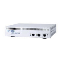
Nortel Contivity 1100 Manual (44 pages)
Brand:
Nortel
| Category:
Network Router
| Size: 1.14 MB
Table of Contents
Restricted Rights Legend
2
Table of Contents
5
Before You Begin
7
Preface
7
Text Conventions
7
Related Publications
8
Acronyms
9
Hard-Copy Technical Manuals
9
How to Get Help
10
Chapter 1 Overview
11
Default Configuration
12
DHCP Server
12
Pppoe
13
Branch Office Quick Start Utility
14
DNS Proxy
15
Compact Flash Disk
16
CLI Commands
18
Chapter 2 Getting Started
21
Default Configuration Parameters
21
DHCP Server
22
Configuring Pppoe
25
Static IP Addressing
27
Branch Office Quick Start
28
Enterprise Environment
29
Service Provider Environment
31
Connecting for Internet Access
35
Configuring a DNS Server
37
Compact Flash Disk
39
Branch Office Quick Start Template
41
Nortel Contivity 1100 Connecting Manual (6 pages)
Connecting for VPN Access
Brand:
Nortel
| Category:
Network Router
| Size: 0.13 MB
Table of Contents
READ ME FIRST: Connecting for VPN Access
1
Before You Begin
1
Check that You Received These Items
1
Cable the VPN Router and Turn the Power on
2
Make Sure that Your Pcs Can Obtain IP Addresses Automatically
3
Test the VPN Router and Start the Branch Office Quick-Start Tool
3
DHCP Instructions
3
Pppoe Instructions
4
Static IP Instructions
4
The Add IP Address Window Appears.
5
Advertisement
Related Products
Nortel Contivity 1050
Nortel Contivity 100
Nortel Contivity1510D
Nortel Contivity Extranet Switch 4600
Nortel Contivity VPN Client
Nortel Contivity Extranet Switch 2500
Nortel Contivity 600
Nortel Contivity 1600
Nortel Contact Center Manager
Nortel Contact Recording
Nortel Categories
IP Phone
Telephone
Switch
Software
Server
More Nortel Manuals
Login
Sign In
OR
Sign in with Facebook
Sign in with Google
Upload manual
Upload from disk
Upload from URL