Sign In
Upload
Manuals
Brands
NetApp Manuals
Speaker System
EF570
NetApp EF570 All-Flash Array Manuals
Manuals and User Guides for NetApp EF570 All-Flash Array. We have
2
NetApp EF570 All-Flash Array manuals available for free PDF download: Feature Overview Manual, Install And Setup
NetApp EF570 Feature Overview Manual (94 pages)
With SANtricity 11.50.2
Brand:
NetApp
| Category:
Speaker System
| Size: 5.71 MB
Table of Contents
Table of Contents
2
1 Introduction
6
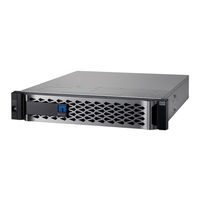
Figure 1) New-Generation Netapp EF570 All-Flash Array with Bezel on and off
6
Figure 2) EF-Series 4KB Random Read Performance Improvements over Time
7
Figure 3) EF570 Controller with Ports Identified
8
2 Santricity Management Features
9
Deployment
9
Figure 4) Decision Tree for Santricity Management Components to Install
10
Figure 5) Managing a Single EF570 with Santricity System Manager
10
Figure 6) Managing Multiple EF570 Systems and E5700 Systems with EMW and System Manager
11
Santricity Unified Manager
12
Figure 7) Managing a Mixed-Array Environment with Santricity Storage Manager and System Manager
12
Figure 8) Final Dialog Box in the Web Services Proxy Installation Wizard
13
Santricity Unified Manager Navigation
14
Figure 9) Santricity Unified Manager Login Page
14
Figure 10) New Santricity Unified Manager Landing Page-Discover and Add Arrays
15
Figure 11) Santricity Unified Manager Landing Page
15
Figure 12) Creating a Group to Organize Arrays in Santricity Unified Manager
16
Figure 13) Creating a Group in Unified Manager
16
Figure 14) Santricity Unified Manager Showing Newly Created Group
17
Figure 15) Santricity Unified Manager Operations View
17
Figure 16) Santricity Unified Manager os Software Repository View
18
Figure 17) Santricity Unified Manager Upgrade os
18
Figure 18) Santricity Unified Manager Upgrade os Options
19
Figure 19) Santricity os Confirm Transfer
19
Figure 20) Upgrade Status
20
Figure 21) os Software Upgrade Successful
20
Figure 22) New Santricity os Version Displayed
20
Santricity System Manager
21
Table 1) Management Use Cases
21
Figure 23) Santricity System Manager Home Page
25
Figure 24) System Manager Storage Page
26
Figure 25) System Manager Hardware Page
26
Figure 26) System Manager Settings Page with New Security Tiles
27
Figure 27) System Manager Support Page
27
Figure 28) System Manager Support Center
28
Table 2) Built-In Roles and Associated Permissions
29
Table 3) LDAP/RBAC Required Fields and Definitions
30
Figure 29) Santricity System Manager Directory Server Setup Wizard
31
Figure 30) Role Mapping Tab in the Directory Server Settings Wizard
32
Figure 31) Santricity System Manager Views Change Based on User Permission Level
33
Figure 32) Initial Step Required to Set up Web Server Certificates
34
Figure 33) Expanded Santricity System Manager Certificates Tile
34
Santricity Storage Features
36
Table 4) Santricity Host Types and Associated Failover Behavior in Santricity 11.50.X
37
Table 5) Santricity 11.50.X Features for Long-Term Reliability
37
Table 6) EF570 Standard Features that Are Included with Santricity 11.50.X
38
Table 7) Santricity 11.50.X Copy Services Features
39
Santricity Management Integration
40
Santricity Web Services Native REST API
40
Table 8) Santricity Apis and Toolkits
40
Table 9) Third Platform Plug-Ins that Use the Santricity Web Services Proxy
40
Figure 34) Opening the API Documentation
41
Figure 35) Example Expanding the Device-ASUP Endpoint
41
Figure 36) REST API Documentation Sample
42
Figure 37) Sample Output from the Try It Out! Button
42
3 Sales Support Tool Enhancements
43
Config Advisor
43
Figure 38) Device-Asup Endpoint Possible Response Codes and Definitions
43
Fusion
44
Figure 39) E-Series and EF-Series Performance Sizing Tool Launched from the Fusion Tool
45
Figure 40) Performance Sizing Report
45
Synergy
46
Hardware Universe
46
Host Utilities
46
4 Santricity Software Specifications for EF570 Hardware
46
Table 10) Santricity Software Boundaries for EF570-Based Storage Systems
46
5 EF570 Hardware Configurations
48
Controller Shelf Configurations
48
Figure 41) EF570 Front View with Bezel
48
Figure 42) EF570 Front View (Open)
48
Figure 43) EF570 Rear View
48
Table 11) EF570 Technical Specifications
49
See the Hardware Universe for Current Supported Drive Availability Information and Encryption Capability
50
By Drive Capacity (FDE, Fips).Controller Host Interface Features
50
Table 12) Available FP-Smids for EF570 Controllers
50
Table 13) FC Host Interface Port Speed and Associated Sfps
51
Table 14) Iscsi Host Interface Port Speed and Associated Sfps
51
Table 15) IB Host Interface Port Speed and Associated Cables and Sfps
51
Hardware LED Definitions
52
Figure 44) EF570 with Optional Hics
52
Table 16) EF570 Controller Shelf LED Definitions (Front Panel)
53
Figure 45) ODP on Front Panel of EF570 Controller Shelf
53
Figure 46) Setting Shelf ID by Using Santricity System Manager
54
Table 17) EF570 Controller Shelf Power and Fan Canister LED Definitions
55
Figure 47) Leds on EF570 Power Fan Canister (Rear View)
55
Figure 48) Viewing System Status Information by Using Santricity System Manager
56
Figure 49) Controller Module and Array Status Leds
56
Table 18) Controller Base Features LED Definitions
57
Figure 50) Ethernet Management Ports on the EF570 Controller Canister
57
Table 19) Ethernet Management Port LED Definitions
58
Table 20) 16Gb Fc/10Gb Iscsi Baseboard Host Port LED Definitions
58
Figure 51) Ports 0A and 0B 16Gb Fc/10Gb Iscsi Baseboard Host Ports
58
Table 21) Drive Expansion Port LED Definitions
59
Figure 52) Leds for Drive Expansion Ports
59
Table 22) 2-Port 100Gb IB HIC LED Definitions
60
Figure 53) Leds on 2-Port 100Gb IB HIC
60
Table 23) 4-Port 12Gb SAS HIC LED Definitions
61
Figure 54) Leds for 4-Port 12Gb SAS HIC
61
Table 24) 4-Port 32Gb FC HIC LED Definitions
62
Figure 55) Leds for 4-Port 32Gb FC HIC
62
Table 25) 4-Port Optical 25Gb Iscsi HIC LED Definitions
63
Figure 56) Leds for 4-Port 25Gb Iscsi HIC
63
Setting Shelf ID with ODP Pushbutton
64
Figure 57) ODP on the DE224C (Front Bezel or End Caps Removed)
64
6 Drive Shelves
65
Figure 58) DE224C Front View with End Caps
65
Figure 59) DE224C Front View Without End Caps
65
Figure 60) DE224C Rear View
65
Figure 61) Leds for IOM
66
IOM LED Definitions
66
Table 26) IOM LED Definitions
66
Drive LED Definitions
67
Figure 62) EF570 Drive Carrier Leds
67
Table 27) EF570 Drive LED Definitions
67
Figure 63) EF570 Expansion-Drive Shelf Cabling Example for Maximum DE224C Shelf Configuration
68
Figure 64) EF570 with Mixed 6Gbps and 12Gbps Expansion Shelves
68
Greenfield Installation
68
Drive Shelf Hot Add
69
Figure 65) Drive Shelf Hot-Add Controller Expansion Port 1 Cabling
69
7 Series Product Support
70
Controller Shelf Serial Number
70
Figure 66) Drive Shelf Hot-Add Controller Expansion Port 2 Cabling
70
Figure 67) Controller Shelf SN
71
Figure 68) Santricity System Manager Support Center Tile Showing Chassis Serial Number
71
License Keys
72
Figure 69) Change Feature Pack from Settings>System View
72
Summary
73
Figure 70) Change Feature Pack Option
73
Appendix
74
System Manager Tables
74
Table 28) Storage Array Options: AMW Compared with System Manager
74
Table 29) Disk Pool Options: AMW Compared with System Manager
75
Table 30) Volume Group Options: AMW Compared with System Manager
76
Table 31) Volume Options: AMW Compared with System Manager
78
Table 32) Snapshot Group Options: AMW Compared with System Manager
80
Table 33) Snapshot Image Options: AMW Compared with System Manager
81
Table 34) Snapshot Volume Options: AMW Compared with System Manager
82
Table 35) Volume Copy Options: AMW Compared with System Manager
83
Table 36) Asynchronous Mirroring Options: AMW Compared with System Manager
83
Table 37) Synchronous Mirroring Options: AMW Compared with System Manager
85
Table 38) Host Mapping Options: AMW Compared with System Manager
86
Where to Find Additional Information
93
Version History
93
Table 39) Santricity Upgrade Using Unified Manager
93
Advertisement
NetApp EF570 Install And Setup (16 pages)
12 and 24-drives
Brand:
NetApp
| Category:
Storage
| Size: 0.37 MB
Table of Contents
Table of Contents
2
Install and Set up 12 and 24-Drives
3
Prepare for Installation
3
Install the Hardware
5
Connect the Cables
8
Complete Storage System Setup and Configuration
11
Advertisement
Related Products
NetApp EF Series
NetApp EF550
NetApp EF560
NetApp EF600
NetApp EF300
NetApp EF280
NetApp E2724
NetApp E5460
NetApp E5560
NetApp E5600
NetApp Categories
Storage
Network Hardware
Disk array system
Controller
DC Drives
More NetApp Manuals
Login
Sign In
OR
Sign in with Facebook
Sign in with Google
Upload manual
Upload from disk
Upload from URL