Sign In
Upload
Manuals
Brands
National Instruments Manuals
Desktop
VXIpc-486 599
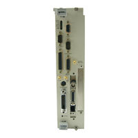
National Instruments VXIpc-486 599 Manuals
Manuals and User Guides for National Instruments VXIpc-486 599. We have
1
National Instruments VXIpc-486 599 manual available for free PDF download: Getting Started
National Instruments VXIpc-486 599 Getting Started (92 pages)
Brand:
National Instruments
| Category:
Desktop
| Size: 0.47 MB
Table of Contents
Table of Contents
6
About this Manual
11
Organization of this Manual
11
Conventions Used in this Manual
12
Customer Communication
13
Related Documentation
13
Chapter 1 Introduction
14
What You Need to Get Started
14
Optional Equipment
14
Optional Software
15
Hardware Description
15
Vxipc-486 Configuration and Installation
16
Factory Configuration
16
Table 2-1. Vxipc-486 Model 500 Series Factory Configuration
16
Configuring the Vxipc-486
17
Figure 2-1. Vxipc-486 Model 500 Series Parts Locator Diagram
17
Configuration Procedure
18
Configuration Options
19
Vxibus Slot and External CLK10 Configuration Options
19
Table 2-2. Vxibus Slot Position and External CLK10 Configuration Options
19
Slot 0 Configurations
20
Non-Slot 0 Configurations
20
MODID Signal Termination
21
System Controller
21
Figure 2-2. MODID Signal Termination Settings
21
Figure 2-3. System Controller Settings
21
CLK10 Generation
22
Vxibus CLK10
22
Figure 2-4. CLK10 Generation Settings
22
Figure 2-5. Vxibus CLK10 Settings
22
External CLK10
23
External CLK10 Termination
23
Figure 2-6. External CLK10 Settings
23
Figure 2-7. External CLK10 Termination Settings
23
External Trigger Input Configuration
24
Figure 2-8. External Trigger Input Circuit
24
Figure 2-9. External Trigger Input Termination Settings
24
External Audio/Trigger Output Configuration
25
Installed System RAM Configuration
25
Table 2-3. External Audio/Trigger Output Configuration Options
25
Table 2-4. Installed RAM Configuration Options
25
Installing and Starting up the Vxipc-486
26
Figure 2-10. Vxipc-486 Model 500 Series Front Panel
27
Chapter 3 BIOS Setup
28
Running Setup
28
Extended Features
29
Table 3-2. Extended BIOS Configuration Parameters
30
National Instruments Software
31
Ni-VXI
31
Labview and Labwindows
32
Appendix B Specifications
33
Cpu
33
Physical
33
Power Requirements
34
Cooling
34
Emissions
34
Operating Environment
34
Storage Environment
34
Ieee 488
34
Vmebus Master/Slave
35
Vmebus System Controller
35
Vxibus
36
Appendix C Front Panel Indicators
37
Table C-1. Front Panel LED Indications
37
Appendix D Connectors
39
Keyboard
39
Figure D-1. KEYBOARD Connector
39
Table D-1. KEYBOARD Connector Signals
39
Vga
40
Figure D-2. VGA Connector
40
Table D-2. VGA Connector Signals
40
Com1
41
Figure D-3. COM1 Connector
41
Table D-3. COM1 Connector Signals
41
Com2/Gpio
42
Figure D-4. COM2/GPIO Connector
42
Table D-4A. COM2/GPIO Connector COM2 Signals
42
Table D-4B. COM2/GPIO Connector GPIO Signals
42
Lpt
43
Figure D-5. LPT Connector
43
Table D-5. LPT Connector Signals
43
Floppy Disk Drive
44
Figure D-6. DISK DRIVE Connector
44
Table D-6. DISK DRIVE Connector Signals
44
Gpib
45
Figure D-7. GPIB Connector
45
Table D-7. GPIB Connector Signals
45
External CLK10
46
Figure D-8. EXT CLK Connector
46
Table D-8. EXT CLK Connector Signals
46
External Trigger Input
47
Figure D-9. TRG in Connector
47
Table D-9. TRG in Connector Signals
47
External Audio/Trigger Output
48
Figure D-10. AUDIO/TRG out Connector
48
Table D-10. AUDIO/TRG out Connector Signals
48
Vxibus P1 and P2
49
Figure D-11. Vxibus Connector
49
Table D-11. Vxibus P1 Connector Signals
49
Table D-12. Vxibus P2 Connector Signals
50
Modifying and Installing I/O Expansion Boards
51
Appendix Fvxipc-486 Plug-In Boards
52
Height of Vxipc-486 Plug-In Boards
52
Figure F-1. Height Comparison of PC Boards Versus PC at Boards
52
Figure F-2. Installing PC-Height Boards in a Vxipc-486 System
53
Length of Vxipc-486 Plug-In Boards
54
Figure F-3. Installing PC AT-Height Boards in a Vxipc-486 System
54
Figure F-4. Vxipc-486 Expansion Kit with no Boards Installed
55
Figure F-5. Kit Number 776713-02 for Two-Board Expansion (Model 500 Series
55
Figure F-6. First Board 8.2 In. Long or Less
56
Figure F-7. First Board between 8.2 In. and 13.4 In. Long
56
Figure F-8. both Boards 8.2 In. Long or Less
56
Figure F-9. First Board Less than 8.2 In. Long, Second Board 8.2 In. Long or Less, but Longer than the First Board
56
Figure F-10. First Board 8.2 In. Long or Less, Second Board over One Inch Shorter than First Board
57
Figure F-11. First Board 8.2 In. Long or Less, Second Board between 8.2 In. and 13.4 In. Long
57
Figure F-12. both Boards between 8.2 In. and 13.4 In. Long
57
Figure F-13. Second Board Full 13.4 In. Long
58
Figure F-14. First Board 8.2 In. Long or Less, Second Board Full 13.4 In. Long
58
Figure F-15. First Board between 8.2 In. and 13.4 In. Long, Second Board Full 13.4 In. Long
58
Vxipc-486 Hardware Configuration
59
Table G-1. Vxipc-486 Model 500 Series Memory Map
59
Table G-2. Vxipc-486 Model 500 Series I/O Address Map
60
Table G-3. Vxipc-486 Model 500 Series Interrupt Line Use
61
Table G-4. Vxipc-486 Model 500 Series DMA Channel Use
62
Configuring the Super VGA Option
63
Introduction
63
Modifying the System Settings
63
Installing the Super VGA Drivers
64
Appendix I Common Questions
65
Appendix J Troubleshooting
72
Customer Communication
76
Glossary
82
Index
88
Advertisement
Advertisement
Related Products
National Instruments VXIpc-486 500 Series
National Instruments VXIpc-486 566
National Instruments VXIpc-486
National Instruments VXIpc-860
National Instruments VXIpc-771
National Instruments VXIpc-770
National Instruments VXIpc-872B
National Instruments VXIpc-874B
National Instruments VXIpc-875B
National Instruments VXIpc 770 Series
National Instruments Categories
Control Unit
I/O Systems
Controller
Computer Hardware
Measuring Instruments
More National Instruments Manuals
Login
Sign In
OR
Sign in with Facebook
Sign in with Google
Upload manual
Upload from disk
Upload from URL