User Manuals: National Instruments PCI-6071E Card
Manuals and User Guides for National Instruments PCI-6071E Card. We have 4 National Instruments PCI-6071E Card manuals available for free PDF download: User Manual, Programmer's Manual
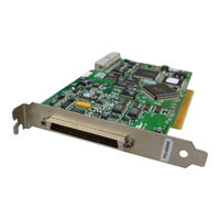
National Instruments PCI-6071E User Manual (265 pages)
Brand: National Instruments
|
Category: Computer Hardware
|
Size: 3.59 MB
Table of Contents
-
Conventions13
-
Labview15
-
DAQ Hardware20
-
Daq-Stc21
-
Scxi23
-
Scc24
-
5B Series24
-
Analog Input35
-
Mux35
-
Ai Fifo36
-
Dither42
-
Example 146
-
Example 247
-
NI-Daqmx63
-
Dacs82
-
Dac Fifo82
-
Buffered85
-
Non-Buffered86
-
Digital I/O98
-
Counters107
-
Start Trigger107
-
Pause Trigger108
-
CTR 0 out Pin112
-
Inputs117
-
Outputs117
-
Digital Routing119
-
RTSI Triggers124
-
Bus Interface128
-
MITE and Daqpnp128
-
Programmed I/O129
-
Triggering131
-
Level Triggering134
Advertisement

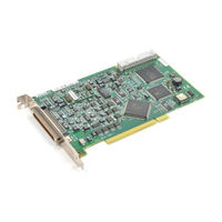
National Instruments PCI-6071E User Manual (265 pages)
Brand: National Instruments
|
Category: I/O Systems
|
Size: 3.59 MB
Table of Contents
-
Conventions13
-
Labview15
-
DAQ Hardware20
-
Daq-Stc21
-
Scxi23
-
Scc24
-
5B Series24
-
Analog Input35
-
Mux35
-
Ai Fifo36
-
Dither42
-
Example 146
-
Example 247
-
NI-Daqmx63
-
Dacs82
-
Dac Fifo82
-
Buffered85
-
Non-Buffered86
-
Digital I/O98
-
Counters107
-
Start Trigger107
-
Pause Trigger108
-
CTR 0 out Pin112
-
Inputs117
-
Outputs117
-
Digital Routing119
-
RTSI Triggers124
-
Bus Interface128
-
MITE and Daqpnp128
-
Programmed I/O129
-
Triggering131
-
Level Triggering134
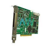
National Instruments PCI-6071E User Manual (161 pages)
PCI E Series Multifunction I/O Boards for PCI Bus Computers
Brand: National Instruments
|
Category: Computer Hardware
|
Size: 1 MB
Table of Contents
-
-
-
-
Analog Input27
-
Input Mode27
-
Dither32
-
Digital I/O40
-
-
-
-
-
-
TRIG1 Signal73
-
TRIG2 Signal74
-
-
Bus Interface104
-
Input Impedance108
-
-
-
Noise110
-
Compatibility111
-
Advertisement
National Instruments PCI-6071E Programmer's Manual (162 pages)
Register-Level Programmer Manual, Multifunction I/O Boards for PCI Bus Computers, Register-Level
Brand: National Instruments
|
Category: I/O Systems
|
Size: 1.04 MB
Table of Contents
-
-
-
-
Register Map40
-
-
-
-
Example 480
-
Example 584
-
Example 686
-
Example 788
-
Example 890
-
-
Example 992
-
-
DMA Programming120
-
-
About the EEPROM123
-
-
Calibration Dacs136
-
-
Advertisement
Related Products
- National Instruments DAQ PCI-6023E
- National Instruments DAQ PCI-6024E
- National Instruments DAQ PCI-6025E
- National Instruments PCI-6031E
- National Instruments PCI-6032E
- National Instruments PCI-6033E
- National Instruments PCI-6035E
- National Instruments PCI-6036E
- National Instruments PCI-6062E
- National Instruments PCI-6034E