Sign In
Upload
Manuals
Brands
National Instruments Manuals
Computer Hardware
PC-DIO-24/PnP
National Instruments PC-DIO-24/PnP Manuals
Manuals and User Guides for National Instruments PC-DIO-24/PnP. We have
1
National Instruments PC-DIO-24/PnP manual available for free PDF download: User Manual
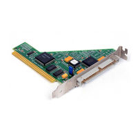
National Instruments PC-DIO-24/PnP User Manual (107 pages)
24-bit Digital I/O Board for ISA Computers
Brand:
National Instruments
| Category:
Computer Hardware
| Size: 1.04 MB
Table of Contents
User Manual
1
Important Information
3
Table of Contents
5
About this Manual
9
Organization of this Manual
9
Conventions Used in this Manual
10
National Instruments Documentation
12
Related Documentation
13
Customer Communication
13
Chapter 1 Introduction
14
About the PC-DIO-24/Pnp
14
What You Need to Get Started
15
Software Programming Choices
15
National Instruments Application Software
15
NI-DAQ Driver Software
16
Register-Level Programming
17
Figure 1-1. the Relationship between the Programming Environment
17
Optional Equipment
18
Custom Cables
18
Unpacking
20
Chapter 2 Installation and Configuration
21
Installation
21
Figure 2-1. Jumper W1 Location
21
Hardware Configuration
22
Plug and Play
22
Base I/O Address and Interrupt Selection
23
Chapter 3 Signal Connections
24
I/O Connector
24
Figure 3-1. Digital I/O Connector Pin Assignments
25
Signal Descriptions
26
Port C Pin Assignments
26
Table 3-1. Signal Descriptions
26
Digital I/O Signal Connections
27
Table 3-2. Port C Signal Assignments
27
Figure 3-2. Digital I/O Connections
29
Power Connections
30
Digital I/O Power-Up State Selection
30
High DIO Power-Up State
30
Figure 3-3. DIO Channel Configured for High DIO Power-Up State with External Load
31
Low DIO Power-Up State
32
Figure 3-4. DIO Channel Configured for Low DIO Power-Up State with External Load
32
Timing Specifications
33
Table 3-3. Timing Signal Descriptions
33
Figure 3-5. Mode 1 Timing Specification for Input Transfers
35
Mode 1 Input Timing
35
Figure 3-6. Mode 1 Timing Specification for Output Transfers
36
Mode 1 Output Timing
36
Figure 3-7. Mode 2 Timing Specification for Bidirectional Transfers
37
Mode 2 Bidirectional Timing
37
Chapter 4 Theory of Operation
38
Functional Overview
38
Figure 4-1. PC-DIO-24/Pnp Block Diagram
38
82C55A Programmable Peripheral Interface
39
Bus Interface
39
Bus Transceivers
39
Interrupt Control Circuitry
39
Digital I/O Connector
40
Appendix A Specifications
41
Input Signals
41
Output Signals
42
Power Requirement
42
Transfer Rates
43
Appendix B
44
OKI 82C55A Data Sheet
44
Appendix C Register-Level Programming
61
Introduction
61
Register Map
63
Register Description for the 82C55A
63
Table C-1. PC-DIO-24/Pnp Address Map
63
Figure C-1. Control Word Formats for the 82C55A
64
Register Description for the Interrupt Control Registers
65
Table C-2. Port C Set/Reset Control Words
65
Interrupt Control Register 1 (Pnp Board Only
66
Interrupt Control Register 2 (Pnp Board Only
67
Programming Considerations for the 82C55A
68
Mode 0
68
Modes of Operation for the 82C55A
68
Mode 0-Basic I/O
69
Single Bit Set/Reset Feature
69
Table C-3. Mode 0 I/O Configurations
69
Mode 0 Programming Example
70
Mode 1-Strobed Input
71
Figure C-2. Port C Pin Assignments, Mode 1 Input
73
Mode 1 Input Programming Example
73
Mode 1-Strobed Output
74
Figure C-3. Port C Pin Assignments, Mode 1 Output
76
Mode 1 Output Programming Example
76
Figure C-4. Port a Configured as a Bidirectional Data Bus in Mode 2
77
Mode 2-Bidirectional Bus
77
Figure C-5. Port C Pin Assignments, Mode 2
79
Mode 2 Programming Example
79
Interrupt Programming Examples for the 82C55A
80
Interrupt Handling
82
Appendix D Register-Level Programming
82
Differences between the PC-DIO-24Pnp and the PC-DIO-24
84
Table D-1. Comparison of Characteristics
84
Configuration
85
Table D-2. PC-DIO-24 Factory-Set Jumper and Switch Settings
85
Base I/O Address Settings
86
Figure D-1. PC-DIO-24 Parts Locator Diagram
86
Figure D-2. Example Base I/O Address Switch Settings
87
Interrupt Selection
88
Table D-3. Example Switch Settings with Corresponding Base I/O Address and I/O Address Space
88
Interrupt Enable Settings
89
Interrupt Level Settings
89
Figure D-3. Interrupt Enable Jumper Settings
89
Figure D-4. Interrupt Jumper Setting for IRQ5 (Factory Setting)
89
Installation
90
Appendix E Customer Communication
91
Electronic Services
91
Telephone and Fax Support
92
Special Characters
102
Advertisement
Advertisement
Related Products
National Instruments DAQ PCI-6110E
National Instruments PCI-6031E
National Instruments PCI-6033E
National Instruments PCMCIA-232
National Instruments PCI-232
National Instruments PCI-CAN
National Instruments NI PCI-7813R
National Instruments PCI-5114
National Instruments PCI-6521
National Instruments DAQ X NI PCIe-6320
National Instruments Categories
Control Unit
I/O Systems
Controller
Computer Hardware
Measuring Instruments
More National Instruments Manuals
Login
Sign In
OR
Sign in with Facebook
Sign in with Google
Upload manual
Upload from disk
Upload from URL