Sign In
Upload
Manuals
Brands
National Instruments Manuals
Controller
cRIO-9047
User Manuals: National Instruments cRIO-9047 Controller
Manuals and User Guides for National Instruments cRIO-9047 Controller. We have
1
National Instruments cRIO-9047 Controller manual available for free PDF download: User Manual
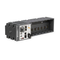
National Instruments cRIO-9047 User Manual (111 pages)
Embedded CompactRIO Controller with Real-Time Processor and Reconfigurable FPGA
Brand:
National Instruments
| Category:
Controller
| Size: 7.05 MB
Table of Contents
Table of Contents
2
Configuring the Crio-904X
3
Connecting the Crio-904X to the Host Computer Using USB
3
Finding the Crio-904X on the Network (DHCP)
4
Configuring Startup Options
4
Connecting the Crio-904X to the Host Computer or Network Using Ethernet
4
Crio-904X Startup Options
5
Crio-904X Features
6
Ports and Connectors
6
USB 3.1 Type-C Dual Role
7
USB 3.1 Type-C with Displayport Alt Mode
7
NI USB Type-C Adapters for Crio-904X
8
NI USB Type-C Cables for Crio-904X
8
Signal Descriptions
8
Power Connector
8
Power Connector Pinout
9
Power Accessories
9
SD Card Removable Storage
9
RS-232 Serial Port
10
SD Card Slot Cover
10
Crio-904X SD Storage Accessories
10
RS-232 Serial Port Pinout
11
RS-232 Serial Port Accessories
11
RS-485 Serial Port
11
RS-485 Serial Port Pinout
12
USB 2.0 Type-A
12
RS-485 Serial Port Accessory
12
NI Cables with Retention for Crio-904X
12
Buttons
12
USER1 Button
13
RESET Button
13
Reset Button Behavior
13
Troubleshooting Network Connectivity
14
CMOS Reset Button
14
Crio-904X Front Panel Leds
14
POWER LED Indicators
14
STATUS LED Indicators
15
Ethernet LED Indicators
17
SD in Use LED Indicator
17
Chassis Grounding Screw
18
Internal Real-Time Clock
18
Digital Routing
19
Clock Routing
19
Clock Routing Circuitry of the Crio-904X
19
80 Mhz Timebase
20
20 Mhz and 100 Khz Timebases
20
40 Mhz Onboard Clock
20
Synchronization Across a Network
20
Network-Based Synchronization
21
Differences between IEEE 802.1AS-2011 and IEEE 1588-2008
21
IEEE 1588 External Switch Requirements
22
CMOS Battery
22
Installing the Module Immobilization Accessory
22
Module Immobilization Accessory Dimensions
24
8-Slot Crio-904X Module Immobilization Accessory Dimension
25
Slot Crio-904X Module Immobilization Accessory Dimensions
25
Alternate Mounting Configurations
27
Crio-904X Cooling Dimensions
27
Mounting Requirements for the Crio-904X
27
Ambient Temperature Location
28
CRIO-904X Cabling Clearance
28
Dimensions
28
CRIO-904X 4-Slot Controller Front Dimension
29
CRIO-904X 8-Slot Controller Front Dimensions
29
Crio-904X Side Dimensions
29
Mounting on a Flat Surface
29
Mounting the 4-Slot Crio-904X Directly on a Flat Surface
30
Mounting the 8-Slot Crio-904X Directly on a Flat Surface
31
Surface Mounting Dimensions
31
4-Slot Crio-904X Surface Mounting Dimensions
32
8-Slot Crio-904X Surface Mounting Dimensions
32
Mounting on a Panel
32
Mounting the 4-Slot Crio-904X on a Panel
33
Mounting the 8-Slot Crio-904X on a Panel
33
4-Slot Crio-904X Panel Mounting Dimensions
34
8-Slot Crio-904X Panel Mounting Dimensions
34
Mounting on a DIN Rail
34
Panel Mounting Dimensions
34
Mounting the 4-Slot Crio-904X on a DIN Rail
35
Clipping the Controller on a DIN Rail
36
Mounting the 8-Slot Crio-904X on a DIN Rail
36
Mounting on a Desktop
37
Mounting on a Rack
37
Mounting the 4-Slot Crio-904X on a Desktop
37
Desktop Mounting Dimensions
38
Mounting the 8-Slot Crio-904X on a Desktop
38
4-Slot Crio-904X Desktop Mounting Dimensions
39
8-Slot Crio-904X Desktop Mounting Dimensions
39
Mounting the Controller
25
BIOS Configuration
40
Resetting the System CMOS and BIOS Settings
40
Power-On Self Test Warning Messages
40
BIOS Setup Utility
41
Launching the BIOS Setup Utility
41
BIOS Setup Utility Keyboard Navigation
41
Navigation Keys
41
Main Setup Menu
42
Advanced Setup Menu
42
Power/Wake Configuration Submenu
43
SATA Drives Submenu
43
CPU Configuration Submenu
43
USB Configuration Submenu
43
Boot Setup Menu
44
Boot Settings Configuration Submenu
44
Save & Exit Menu
45
Restore Defaults
45
Save as User Defaults
45
Restore User Defaults
45
Choosing Your Programming Mode
46
Analog Input with NI-Daqmx
47
Supported Programming Modes for Popular Tasks
47
Analog Input Timing Signals
48
Analog Input Triggering Signal
48
Hardware-Timed Single Point (HWTSP) Mode
48
AI Sample Clock Signal
49
AI Sample Clock Timebase Signal
49
AI Sample Clock Timing Options
49
Routing the Sample Clock to an Output Terminal
49
AI Start Trigger Signal
50
Routing AI Start Trigger to an Output Terminal
50
Using a Digital Source
50
Using an Analog Source
50
Reference Trigger Final Buffer
51
Routing the Reference Trigger Signal to an Output Terminal
51
AI Convert Clock Signal Behavior for Analog Input Modules
52
AI Pause Trigger Signal
52
Scanned Modules
52
Delta-Sigma Modules
53
Simultaneous Sample-And-Hold Modules
53
Slow Sample Rate Modules
53
Analog Output Data Generation Methods
54
Analog Output with NI-Daqmx
54
Getting Started with AI Applications in Software
54
Software-Timed Generations
54
Buffered Analog Input
55
Hardware-Timed Generations
55
Analog Output Timing Signals
56
Analog Output Triggering Signals
56
AO Sample Clock Signal
56
Analog Output Timing Options
57
AO Sample Clock Timebase Signal
57
AO Start Trigger Signal
57
Routing AO Sample Clock to an Output Terminal
57
AO Pause Trigger Signal
58
AO Pause Trigger with the Onboard Clock Source
58
Using a Time Source
58
Digital Input/Output with NI-Daqmx
59
Getting Started with AO Applications in Software
59
Minimizing Glitches on the Output Signal
59
Digital Input
60
Serial DIO Versus Parallel DIO Modules
60
Static DIO
60
DI Sample Clock Signal
61
Digital Input Timing Signals
61
Digital Input Triggering Signals
61
DI Sample Clock Timebase Signal
62
DI Sample Clock Timing Options
62
Routing DI Sample Clock to an Output Terminal
62
Using an Internal Source
62
DI Start Trigger Signal
63
Routing DI Start Trigger to an Output Terminal
63
Using an External Source
63
DI Reference Trigger Signal
64
Routing DI Reference Trigger Signal to an Output Terminal
64
DI Pause Trigger Signal
65
Digital Input Filters
65
Filter Example
65
Getting Started with DI Applications in Software
65
Buffered Change Detection Acquisition
66
Change Detection Acquisition
66
Change Detection Event
66
Digital Output
66
Buffered Digital Output
67
Digital Output Data Generation Methods
67
Digital Output Timing Signals
68
Digital Output Triggering Signals
68
Digital Output Timing Options
69
DO Sample Clock Signal
69
DO Sample Clock Timebase Signal
69
DO Start Trigger Signal
69
DO Pause Trigger Signal
70
DO Pause Trigger with the Onboard Clock Source
70
Routing DO Start Trigger Signal to an Output Terminal
70
Digital Input/Output Configuration for ni 9401
71
Getting Started with DO Applications in Software
71
PFI with NI-Daqmx
71
PFI Filter Example
72
PFI Filters
72
Selectable PFI Filter Settings
72
Controller Counter 0 and Frequency Generator
73
Counter Timing Engine
73
Counters with NI-Daqmx
73
Arm Start Trigger
74
Counter Timing Measurements
74
Counter Triggering
74
Default Counter/Timer Routing
75
Other Counter Features
75
Pause Trigger
75
Start Trigger
75
Cascading Counters
76
Prescaling
76
Synchronization Modes
76
80 Mhz Source Mode
77
Counter Input Applications
77
Counting Edges
77
External or Internal Source Less than 20 Mhz
77
Buffered (Sample Clock) Edge Counting
78
Single Point (On-Demand) Edge Counting
78
Controlling the Direction of Counting
79
Pulse-Width Measurement
79
Implicit Buffered Pulse-Width Measurement
80
Single Pulse-Width Measurement
80
Pulse Measurement
81
Sample Clocked Buffered Pulse-Width Measurement
81
Implicit Buffered Pulse Measurement
82
Sample Clocked Buffered Pulse Measurement
82
Single Pulse Measurement
82
Implicit Buffered Semi-Period Measurement
83
Semi-Period Measurement
83
Single Semi-Period Measurement
83
Frequency Measurement
84
Pulse Versus Semi-Period Measurements
84
High Frequency with Two Counters
85
Low Frequency with One Counter
85
Large Range of Frequencies with Two Counters
86
Sample Clocked Buffered Frequency Measurement
87
Choosing a Method for Measuring Frequency
88
Sample Clocked Buffered Frequency Measurement (Averaging)
88
Frequency Measurement Methods
89
One Counter
89
Two Counter High Frequency
89
Two Counter Large Range
89
5 Mhz Frequency Measurement Methods
90
50 Khz Frequency Measurement Methods
90
Which Method Is Best?
90
Measurements Using Quadrature Encoders
92
Period Measurement
92
Position Measurement
92
X1 Encoding
92
Channel Z Behavior
93
X2 Encoding
93
Buffered (Sample Clock) Position Measurement
94
Channel Z Reload with X4 Decoding
94
Measurements Using Two Pulse Encoders
94
Buffered Position Measurement
95
Single Two-Signal Edge-Separation Measurement
95
Two-Signal Edge-Separation Measurement
95
Implicit Buffered Two-Signal Edge-Separation Measurement
96
Sample Clocked Buffered Two-Signal Separation Measurement
96
Counter Output Applications
97
Simple Pulse Generation
97
Pulse Train Generation
98
Single Pulse Generation with Start Trigger
98
Finite Pulse Train Generation
99
Retriggerable Pulse or Pulse Train Generation
99
Continuous Pulse Train Generation
100
Retriggerable Single Pulse Generation False
100
Retriggerable Single Pulse Generation with Initial Delay on Retrigger
100
Buffered Pulse Train Generation
101
Finite Implicit Buffered Pulse Train Generation
101
Continuous Buffered Implicit Pulse Train Generation
102
Finite Buffered Sample Clocked Pulse Train Generation
102
Continuous Buffered Sample Clocked Pulse Train Generation
103
Frequency Generation
103
Using the Frequency Generator
103
Frequency Division
104
Frequency Generator Block Diagram
104
Frequency Generator Output Waveform
104
Counter Timing Signals
105
Pulse Generation for ETS
105
Counter Applications and Counter N Source
106
Counter N Source Signal
106
Routing a Signal to Counter N Source
106
Counter N Aux Signal
107
Counter N Gate Signal
107
Routing a Signal to Counter N Gate
107
Routing Counter N Source to an Output Terminal
107
Counter N A, Counter N B, and Counter N Z Signals
108
Counter N HW Arm Signal
108
Counter N Up_Down Signal
108
Routing Signals to A, B, and Z Counter Inputs
108
Counter N Sample Clock Signal
109
Routing Counter N Sample Clock to an Output Terminal
109
Counter N Internal Output and Counter N TC Signals
110
Frequency Output Signal
110
Worldwide Support and Services
110
Advertisement
Advertisement
Related Products
National Instruments cRIO-904 Series
National Instruments cRIO-9041
National Instruments cRIO-9040
National Instruments cRIO-9042
National Instruments cRIO-9045
National Instruments cRIO-9046
National Instruments cRIO-9048
National Instruments cRIO-9049
National Instruments cRIO-9043
National Instruments CompactRIO cRIO-9002
National Instruments Categories
Control Unit
I/O Systems
Controller
Computer Hardware
Measuring Instruments
More National Instruments Manuals
Login
Sign In
OR
Sign in with Facebook
Sign in with Google
Upload manual
Upload from disk
Upload from URL