Sign In
Upload
Manuals
Brands
NAiS Manuals
Controller
FP0-C14RS
User Manuals: NAiS FP0-C14RS Control Unit
Manuals and User Guides for NAiS FP0-C14RS Control Unit. We have
1
NAiS FP0-C14RS Control Unit manual available for free PDF download: Hardware Manual
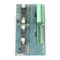
NAiS FP0-C14RS Hardware Manual (173 pages)
Brand:
NAiS
| Category:
Controller
| Size: 23.26 MB
Table of Contents
Table of Contents
6
Components
13
Control Units
13
Expansion I/O Units
14
Expansion Units
14
Overview
13
Chapter 1 Overview
14
Components
14
Intelligent Unit
15
Expansion Possibilities
16
Combination Possibilities
17
Relay Output Type Units
17
Transistor Output Type Units
18
Programming Tools
19
Chapter 2 Control Units
21
Control Unit Types
21
General Specifications
21
Weight
21
Input Specifications
21
Limitations on Number of Simultaneous Input
21
Output Specifications
21
Performance Specifications
21
Transistor Output Type
21
(C16P/C16Cp/C32P/C32Cp)
21
(C16T/C16Ct/C32T/C32Ct)
21
Pin Layouts
22
C10Rs/C10Crs/C10Rm/C10Crm
22
C14Rs/C14Crs/C14Rm/C14Crm
22
C16T/C16Ct
23
Chapter 3 Expansion I/O Units
23
Parts and Terminology
23
Mode Switch
26
Status Indicator Leds
26
Tool Port
26
Specifications
27
General Specifications
27
Current Consumed by the Control Unit
28
Index
31
Input Specifications
34
Limitations on Number of Simultaneous Input on Points
35
Output Specifications
36
Relay Output Type
36
Transistor Output Type
37
Internal Circuit Diagram
38
Relay Output Type
38
Relay Output Type (C10RS/C10CRS/C10RM/C10CRM/C14RS/C14CRS/C14RM/C14CRM)
38
C16P/C16Cp
44
Chapter 3 Expansion I\/O Units
47
Expansion Input Units (E8X/E16X)
47
Relay Output Type (E8RS/E8RM/E16RS/E16RM)
47
Transistor Output Type
47
NPN Open Collector Type (E16T/E32T)
47
PNP Open Collector Type (E16P/E32P)
47
Parts and Terminology
49
Specifications
52
Limitations on Number of Simultaneous Input on Points
53
Output Specifications
54
Relay Output Type
54
(E8Rs/E8Rm/E16Rs/E16Rm)
54
Specifications
54
Expansion Output Units
55
Transistor Output Type
55
Internal Circuit Diagram
56
NPN Open Collector Type
57
Transistor Output Type
57
PNP Open Collector Type
59
Expansion Output Units
61
NPN Open Collector Type (E8YT/E16YT)
61
PNP Open Collector Type (E8YP/E16YP)
63
(E8Yp/E16Yp)
63
Pin Layouts
64
E8Rs/E8Rm
64
E16Rs/E16Rm
65
E16T
66
E16P
67
E32T
68
E32P
69
E8X
70
E16X
71
E8Yt
72
E8Yp
72
E16Yt
73
E16Yp
74
Chapter 4 Analog I\/O Unit
75
A/D Conversion Characteristics
75
Parts and Terminology
77
Analog Input Specifications
80
Control Unit
81
Analog Output Specifications
82
Parts and Terminology
75
Analog I/O Terminal
75
Analog Mode Switch Setting
75
Specifications
75
Analog Input Specifications
75
Analog Output Specifications
75
General Specifications
75
Weight
75
D/A Conversion Characteristics
86
Wiring
87
Analog Input Wiring
87
Analog Output Wiring
88
Boosting the Precision of the Thermocouple Range
90
Averaging Function
91
Averaging for Voltage Ranges and Current Ranges
91
Averaging for a Thermocouple Range
92
Chapter 5 I/O Allocation
95
I/O Number
97
Control Unit
98
Expansion I/O Unit
99
Analog I/O Unit
100
Chapter 6 Installation
101
Adding Expansion Units
103
Important Notes
105
Attachment to DIN Rails
108
Installation Using FP0 Slim Type Mounting Plate
109
Installation Using FP0 Flat Type Mounting Plate
110
Chapter 7 Wiring
113
Safety Instructions
115
Interlock Circuit
115
Emergency Stop Circuit
115
Start up Sequence
115
Momentary Power Failures
116
Protecting Power Supply and Output Sections
116
Wiring the Power Supply to the Control Unit
117
Grounding
119
Input Wiring
120
Sensors
120
LED-Equipped Reed Switch
121
Two-Wire Type Sensor
121
LED-Equipped Limit Switch
122
Output Wiring
123
Protective Circuit for Inductive Loads
123
Precautions for Using Capacitive Loads
124
Wiring the Terminal Type
125
Wiring the MOLEX Connector Type
127
Wiring the MIL Connector Type
129
Contact Puller Pin for Rewiring
130
Wiring the RS232C Port
131
Chapter 8 Connecting the I.o.p. Display Panel
135
Connecting the I.O.P. D01/D30/M01/M30
135
Connecting the I.O.P
137
Connection Using the RS232C Port
137
Connection Using the Tool Port
138
The RS232C Port
139
Connection Using the Tool Port
140
Connecting the I.O.P
140
Before Turning on the Power
141
Turning the Power on
144
Chapter 10 Self-Diagnostic and Troubleshooting
147
Chapter 9 Trial Operation
147
Self-Diagnostic Function
147
Allowing Duplicated Output
148
Troubleshooting
149
ERROR/ALARM LED Is on
151
Diagnosing Output Malfunction
152
Communication Error with Programming Software
154
PROTECT ERROR Is Displayed
155
Error Codes
156
Self-Diagnostic Error
157
Syntax Check Error Codes
158
Self-Diagnostic Error Codes
159
Control Unit and Expansion I/O Unit
163
Fp0-C10Rm/C10Crm/C14Rm/C14Crm/E8Rm/E16Rm
163
Fp0-C10Rs/C10Crs/C14Rs/C14Crs/E8Rs/E16Rs
163
Fp0-C16T/C16Ct/C16P/C16Cp/E16T/E16P/E8X/E8Yt/E8Yp
164
Fp0-C32T/C32Ct/C32P/C32Cp/E32T/E32P/E16X/E16Yt/E16Yp
164
A.2 Analog I/O Unit
165
Analog I/O Unit
165
Mounting on DIN Rail
166
FP0 Slim Type Mounting Plate
167
FP0 Flat Type Mounting Plate
168
Record of Changes
171
Advertisement
Advertisement
Related Products
NAiS FP0-C14RM
NAiS FP0-C14CRS
NAiS FP0-C14CRM
NAiS FP0-C10CRS
NAiS FP0-C10CRM
NAiS FP0-C16T
NAiS FP0-C16CT
NAiS FP0-C16P
NAiS FP0-C16CP
NAiS FP0-C10RM
NAiS Categories
Controller
Monitor
Massager
Touch terminals
Timer
More NAiS Manuals
Login
Sign In
OR
Sign in with Facebook
Sign in with Google
Upload manual
Upload from disk
Upload from URL