Sign In
Upload
Manuals
Brands
Myron L Manuals
Controller
758II
Myron L 758II Manuals
Manuals and User Guides for Myron L 758II. We have
1
Myron L 758II manual available for free PDF download: Operation Manual
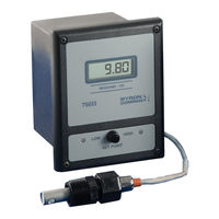
Myron L 758II Operation Manual (76 pages)
CONDUCTIVITY/TDS & RESISTIVITY MONITOR/CONTROLLER
Brand:
Myron L
| Category:
Controller
| Size: 0.87 MB
Table of Contents
750 Series II ILLUSTRATION (758II-121-SC)
5
Table of Contents
6
Introduction
9
Scope
9
Functional Descriptions
9
Applications
9
Specifications
9
Optional Features
10
Accessories
10
Sensors
11
Conductivity/Tds
11
Resistivity
11
Sensor Specifications
11
Order Information
11
How to Order Monitor/Controller
11
How to Order Sensors
11
Range Selection Guide
12
Installation
13
General
13
Mechanical Installation
13
Surface Mounting with SMP (Surface Mounting Plate) Assembly
13
Surface Mounting Without SMP Assembly
13
Panel Mounting
13
Oem Mechanical Installation
14
Circuit Board
14
Analog Meter
14
Digital Display
14
Sensor Insertion / Dip Mount Assemblies
15
Insertion Mode Assembly
15
Alternate Dip Sensor Assembly
15
Electrical Installation
15
Main AC Power Installation
15
5/230 VAC Conversion
16
Connecting the Sensor Cable
16
Modification for US Pharmaceutical 25 (no Temperature Compensation)
16
Solid State Output Connection
17
Piezo Electric Alarm Installation (Option)
17
Remote Alarm Connection (RA Option)
17
Connect to Your Own Alarm or
18
Alarm/Control Relay Connection
18
Connecting Display Harness to Display
18
0-10 VDC Output
19
Connection
19
Voltage Divider
19
RE-RANGE YOUR MONITOR/CONTROLLER (Range Module Installation)
20
Description
20
Installation
20
Changing Analog Meter Scale (Dial)
21
Label Change
22
Options & Accessories Installation
23
Sc/Sco Module (Second Alarm/Control Option)
23
Description
23
Installation
23
Set Point Conversion (SPC) / Reversing Set Point
24
Set Point Adjustment
25
Hysteresis
26
Second Relay Connection
26
Solid State Options
26
4AO MODULE (4-20Ma OPTION)
27
Description
27
Installation
27
Recalibration
28
Converting a Current to a Voltage
30
Tp/Tpo Module (Temperature Option)
31
Description
31
Installation
31
Recalibration
32
TPC "Calibration" Module Procedure
33
Precision Resistor Calibration Procedure
33
System Calibration
34
Alarm/Control Function
34
OEM Installation (Single Display)
36
OEM Installation (Dual Display)
37
Th/Tho Module (Alarm /Control Harness Option)
38
Description
38
Installation
38
DUAL (Stacking) TEMPERATURE MODULE (TPO) & 4-20Ma MODULE (4AO)
43
Description
43
Installation
43
3So/3Se Module (3 Sensor Option)
44
Description
44
Installation
44
Alarm/Control Configuration
45
3Ro/3Re Module (3 Range Option)
47
Description
47
Installation
47
Alarm/Control Configuration
47
3Sro/3Sre Module (Combined 3 Sensor & 3 Range Option)
49
Description
49
Installation
49
Alarm/Control Configuration
50
Pa Piezo Alarm
52
Description
52
Installation
52
Ra Remote Alarm
54
Description
54
Installation
54
IV. Operating Procedures
56
Front Panel Indicators & Controls
56
Red "Set Point" LED Indicator
56
Green "Set Point" LED Indicator
56
Set Point" Switch(Es)
56
Analog Meter or Digital Display
56
Optional Front Panel Items
56
Oem Front Panel Indicators & Controls
57
Red "Set Point" LED Indicator
57
Green "Set Point" LED Indicator
57
Set Point" Switch(Es)
57
Analog Meter or Digital Display
57
Optional Panel Mounted Items
57
Setup Procedures
58
Set Point Conversion (SPC) or Reversing Set Point
58
Check-Out Procedure
58
Set Point Adjustment
58
Hysteresis (Dead Band) Adjustment
58
Component Identification, Calibration and Preventive Care
60
Primary Component Identification
60
Meter Mechanical Zero Procedures
61
Calibration Procedures - Main Circuit Board
61
Electronic Calibration (Circuit Only)
61
Calibration Using Standard Solution
61
Sensor Substitute Calibration
62
Transfer Standard Method
63
Preventive Care
63
VI. Options & Accessories
64
Options Ordered with Monitor/Controller
64
Options & Accessories Ordered Separately
64
Standard Solutions & Buffers
65
VII. Replacement Parts
66
VIII. Warranty
68
IX. Glossary
69
Notes
70
XI. Addendum
71
Conductivity, Tds and Temperature Relationships
71
Advertisement
Advertisement
Related Products
Myron L 758
Myron L 750 II Series
Myron L 757II
Myron L 759II
Myron L 752II
Myron L 753II
Myron L 754II
Myron L 755
Myron L 756
Myron L 757
Myron L Categories
Measuring Instruments
Accessories
Test Equipment
Controller
Monitor
More Myron L Manuals
Login
Sign In
OR
Sign in with Facebook
Sign in with Google
Upload manual
Upload from disk
Upload from URL