Sign In
Upload
Manuals
Brands
mycom Manuals
Air Compressor
200VSD
mycom 200VSD Manuals
Manuals and User Guides for mycom 200VSD. We have
1
mycom 200VSD manual available for free PDF download: Instruction Manual
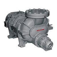
mycom 200VSD Instruction Manual (161 pages)
Screw Compressor
Brand:
mycom
| Category:
Air Compressor
| Size: 11.59 MB
Table of Contents
Preface
2
Revision History
2
Disclaimer Clauses(Exclusion of Warranty Clauses)
3
Warranty and Disclaimer
3
Warranty Clauses
3
Important Information
4
Intended Use of this Product
4
Construction of this Manual
5
Table of Contents
7
Table of Contents
8
Chapter 1 Safety
12
Observation/Prevention
12
Observance (Do's)
12
Do's on Operation
12
Do's on Maintenance
12
Do's on Lockout/Tagout after Shutting off the Power
13
Do's about Personal Protective Equipment(PPE)
13
Do's about Handling of Hazardous and Toxic Substances
13
Do's about the Handling Emergency Situations
13
Do's about Waste Oil, Fluid, and Materials
13
Other Do's
14
Prohibitions (Don'ts)
14
Warnings
15
Types and Meanings of Warnings
15
Safety Labels
15
Residual Risks
17
Safety Devices
20
Emergency Stop Button
20
Breakers for the Main Motor Power and Control Power
20
Compressor Protection Devices
21
Chapter 2 Compressor Specifications and Structure
23
Features of SCV-Series Screw Compressors
23
Model Designation of the Compressor
24
Compressor Specifications
25
Standard Specifications
25
Operation Limits
28
Outer Dimensions
29
Compressor Structure and Mechanism
32
Overview of SCV-Series Screw Compressor
32
Refrigerant Gas Compression Mechanism
33
Gas Suction Phase
33
Compression Phase
34
Discharge Phase
34
Internal Volume Ratio VI
35
What Is the Internal Volume Ratio VI
35
Variable VI Mechanism
36
Why the VI Needs to be Changed
37
Bearings and Balance Piston
40
Shaft Seal
40
Capacity Control
40
Oil Supply Route
40
Chapter 3 Installation
43
General Precautions for Installation
43
Installation Works
43
Unpacking
43
Storage
43
Transportation
43
Preparation for Installation
45
Installation
47
Placement
47
Shaft Alignment between the Compressor and Driving Machine
47
Piping Connection
48
Equipment and Devices for Protection of the Compressor
48
Airtightness Test
49
Vacuuming
49
Lubricating Oil Charge
49
Initial Charge of Lubricating Oil
49
Additional Charge of Lubricating Oil
49
Charge of Refrigerant
49
Checkout after Installation
49
Chapter 4 Compressor and Package Unit Operation
50
Adjustment of VI
50
Overview
50
How to Adjust the VI Setting
50
Lubricating Oil (Refrigerant Oil)
55
Precautions for Selecting the Lubricating Oil
55
Recommended Lubricating Oils
55
Recommended Lubricating Oil for Ammonia Refrigerant
55
Oils for Systems Using Hydrofluorocarbon (HFC) Refrigerants
56
Change of Lubricating Oil Brand
57
Precautions for Handling Lubricating Oil
57
Precautions for Handling Polyalkylene Glycols (PAG)
58
Precautions for Handling Polyolesters (POE) Oil
58
Lubricating Oil Control Criteria
58
Lubricating Oil Replacement Timing
59
After Starting the Initial Operation
59
During Normal Operation
59
Precautions for Operation
60
Prevention of Liquid Flow-Back Operation
60
Purging of Non Condensable Gases
60
When Stopping the Compressor for a Long Time
61
Chapter 5 Maintenance and Inspection
62
Precautions for Maintenance and Inspection
62
Maintenance and Inspection List
64
Daily Management
64
Periodic Inspection
66
Compressor Disassembly Preparation
68
Replacement Parts
69
Refrigerant Gas Recovery
71
Removal of Connections to the Unit
71
Removal of the Compressor from Base Flame
73
Compressor Disassembly Order
74
Disassembly and Inspection
75
Unloader Indicator Block
75
Disassembly
76
Inspection
77
Shaft Seal Block
78
Disassembly
78
Inspection
79
Unloader Cover
80
Disassembly
80
Inspection
81
Unloader Cylinder and Balance Piston Cover
82
Disassembly
82
Inspection
83
Balance Piston Block
84
Disassembly
84
Inspection
85
Bearing Cover
86
Disassembly
86
Inspection
86
Suction Cover and Side Bearings
87
Disassembly
87
Inspection
88
Thrust Bearing Block
89
Disassembly
89
Inspection
90
Rotors and Main Rotor Casing
91
Disassembly
91
Inspection
91
Variable VI Auxiliary Slide Valve and Unloader Slide Valve
92
Disassembly
92
Inspection
93
Bearing Head and Main Bearings
94
Disassembly
94
Inspection
94
Reassembly
95
Bearing Head and Main Bearings
96
Unloader Slide Valve
97
Installing the Rotors
98
Suction Cover and Side Bearings
99
Balance Piston Sleeve
99
Installing the Suction Cover
100
Thrust Bearing Block
101
End Clearance Measurement
103
End Clearance Adjustment Procedure
104
Tightening after Finishing the End Clearance Adjustment
105
Installing the Balance Piston
105
Balance Piston Cover and Unloader Cylinder
106
Unloader Cover
109
Bearing Cover
110
Shaft Seal Block
111
Unloader Indicator
114
Potentiometer
114
Micro-Switches and Micro-Switch Cam
115
Reassembly
115
Chapter 6 Troubleshooting
118
Chapter 7 Related Documents
129
Exploded Views and Sectional Views
129
Parts Configuration Table
134
Lock Nuts
155
Thrust Bearing Gland
156
O-Rings Used
157
List of O-Rings Used
157
Gasket Used
158
Tools for Disassembly
159
Advertisement
Advertisement
Related Products
mycom 200SUD
mycom 200MUD
mycom 200LUD
mycom 200VLD
mycom 200VMD
mycom 200VLG
mycom 200VMG
mycom 200VSG
mycom 2016LMC
mycom 2016MSC
mycom Categories
Air Compressor
Engine
Compressor
Cell Phone
Control Unit
More mycom Manuals
Login
Sign In
OR
Sign in with Facebook
Sign in with Google
Upload manual
Upload from disk
Upload from URL