Sign In
Upload
Manuals
Brands
Motorola Manuals
Controller
MVME162P4 Series
Motorola MVME162P4 Series Manuals
Manuals and User Guides for Motorola MVME162P4 Series. We have
2
Motorola MVME162P4 Series manuals available for free PDF download: Installation And Use Manual
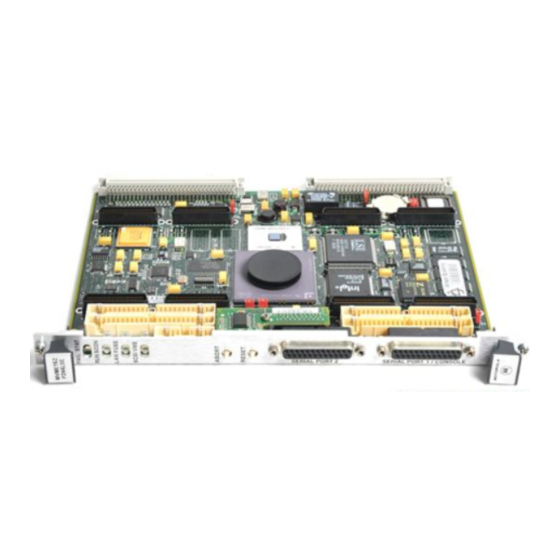
Motorola MVME162P4 Series Installation And Use Manual (146 pages)
VME Embedded Controller
Brand:
Motorola
| Category:
Controller
| Size: 1.19 MB
Table of Contents
Table of Contents
7
Overview of Contents
16
Summary of Changes
16
Comments and Suggestions
17
Conventions Used in this Manual
18
CHAPTER 1 Hardware Preparation and Installation
19
Introduction
19
Getting Started
19
Overview of Installation Procedure
19
Table 1-1. Startup Overview
19
Equipment Required
20
Guidelines for Unpacking
20
ESD Precautions
21
Preparing the Board
22
MVME162P4 Configuration
23
Table 1-2. MVME162P4 Configuration Settings
23
Figure 1-1. MVME162P4 Board Layout
24
VME System Controller (J1)
25
IP Bus Clock (J14)
26
SIM Selection for Serial Port B (J15)
27
Figure 1-2. Serial Interface Module, Connector Side
27
Removal of Existing SIM
28
Table 1-2. Serial Interface Module Part Numbers
28
Installation of New SIM
29
Serial Port 1/Console Clock (J16)
30
Serial Port 2 Clock (J17)
30
IP Bus Strobe (J19)
31
SRAM Backup Power Source (J22)
31
EPROM Size (J23)
32
Flash Write Protection (J24)
33
MC2 DRAM Size (S3)
33
Table 1-3. MC2 DRAM Size Settings
34
General-Purpose Readable Switch (S4 Pin 5)
35
IP DMA Snoop Control (S5 Pins 1/2)
36
Table 1-4. Switch S5 Snoop Control Encoding
36
IP Reset Mode (S5 Pin 3)
37
Flash Write Enable Mode (S5 Pin 4)
38
MCECC DRAM Size (S6)
39
Installation Instructions
40
Table 1-5. MCECC DRAM Size Settings
40
IP Installation on the MVME162P4
41
MVME162P4 Installation
41
System Considerations
44
Serial Connections
46
Figure 1-3. EIA-232-D Connections to MVME712M (Sheet 1 of 6)
47
Figure 1-4. EIA-530 Connections (Sheet 1 of 2)
53
Figure 1-5. EIA-485/EIA-422 Connections
55
CHAPTER 2 Startup and Operation
57
Introduction
57
Front Panel Switches and Indicators
57
Table 2-1. MVME162P4 Front Panel Controls
57
Initial Conditions
58
Applying Power
59
Figure 2-1. Mvme162P4/Firmware System Startup
59
Pre-Startup Checklist
60
Bringing up the Board
61
Table 2-2. Software-Readable Switches
62
Autoboot
65
Romboot
66
Network Boot
67
Restarting the System
68
Reset
68
Abort
69
Break
70
Diagnostic Facilities
70
CHAPTER 3 162Bug Firmware
71
Introduction
71
162Bug Overview
71
162Bug Implementation
73
Memory Requirements
74
Table 3-1. Memory Offsets with 162Bug
74
Using 162Bug
75
Debugger Commands
76
Table 3-2. Debugger Commands
76
Modifying the Environment
79
CNFG - Configure Board Information Block
79
ENV - Set Environment
81
Configuring the 162Bug Parameters
81
Table 3-3. ENV Command Parameters
81
Configuring the Industrypacks
89
CHAPTER 4 Functional Description
93
Introduction
93
Summary of Features
93
Table 4-1. MVME162P4 Features
93
Processor and Memory
94
I/O Implementation
95
Asics
96
Block Diagram
96
Functional Description
96
Figure 4-1. MVME162P4 Block Diagram
97
Data Bus Structure
98
Microprocessor
98
Mc68Xx040 Cache
98
Memory Options
99
Dram
99
Sram
100
About the Battery
101
EPROM and Flash Memory
103
No-Vmebus-Interface Option
99
Battery-Backed-Up RAM and Clock
103
I/O Interfaces
104
Serial Communications Interface
104
Industrypack (IP) Interfaces
107
Ethernet Interface
108
SCSI Interface
109
SCSI Termination
109
Vmebus Interface and Vmechip2
104
Local Resources
109
Programmable Tick Timers
109
Watchdog Timer
110
Software-Programmable Hardware Interrupts
110
Local Bus Timeout
110
Connectors
111
Table 4-2. Local Bus Arbitration Priority
111
Remote Status and Control
112
Local Bus Arbiter
111
CHAPTER 5 Pin Assignments
113
Connector Pin Assignments
113
Industrypack A, B, C, D Connectors
113
Table 5-1. Industrypack Interconnect Signals
114
Remote Reset Connector - J6
115
Table 5-2. Remote Reset Connector J6 Pin Assignments
115
Serial Port Module Connector - J15
116
Table 5-3. Serial Port Module Connector Pin Assignments
116
Serial Port 2 Connector - J18
117
Table 5-4. Serial Connector J18 Pin Assignments
117
Serial Port 1/Console Connector - J25
118
Vmebus Connectors - P1, P2
118
Table 5-5. Serial Connector J25 Pin Assignments
118
Table 5-6. Vmebus Connector P1 Pin Assignments
119
Table 5-7. Vmebus Connector P2 Pin Assignment
120
APPENDIX A Specifications
121
Board Specifications
121
Table A-1. MVME162P4 Specifications
121
Cooling Requirements
122
Special Considerations for Elevated-Temperature Operation
123
EMC Regulatory Compliance
124
APPENDIX B Troubleshooting
125
Solving Startup Problems
125
Table B-1. Troubleshooting MVME162P4 Boards
125
APPENDIX C Network Controller Data
129
Network Controller Modules Supported
129
APPENDIX D Disk/Tape Controller Data
131
Controller Modules Supported
131
Default Configurations
132
IOT Command Parameters
135
APPENDIX E Related Documentation
137
MCG Documents
137
Table E-1. Motorola Computer Group Documents
137
Manufacturers' Documents
138
Table E-2. Manufacturers' Documents
138
Related Specifications
139
Advertisement
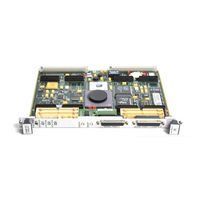
Motorola MVME162P4 Series Installation And Use Manual (20 pages)
VME Embedded Controller
Brand:
Motorola
| Category:
Controller
| Size: 0.05 MB
Advertisement
Related Products
Motorola MVME162P-344 Series
Motorola MVME162P-244 Series
Motorola MVME162P-244L
Motorola MVME162P-244LE
Motorola MVME162P-244LSE
Motorola MVME162P-344S
Motorola MVME162P-344SE
Motorola MVME162P-242LSE
Motorola MVME162P-242E
Motorola MVME162P2 Series
Motorola Categories
Cell Phone
Two-Way Radio
Baby Monitor
Cordless Telephone
Radio
More Motorola Manuals
Login
Sign In
OR
Sign in with Facebook
Sign in with Google
Upload manual
Upload from disk
Upload from URL