Sign In
Upload
Manuals
Brands
Mold-Masters Manuals
Industrial Equipment
Hot Runner
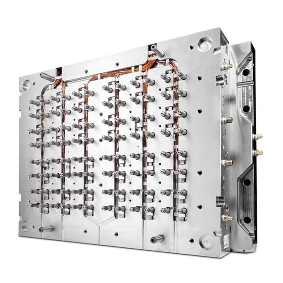
Mold-Masters Hot Runner Equipment Manuals
Manuals and User Guides for Mold-Masters Hot Runner Equipment. We have
3
Mold-Masters Hot Runner Equipment manuals available for free PDF download: User Manual, Troubleshooting Manual
Mold-Masters Hot Runner User Manual (319 pages)
Brand:
Mold-Masters
| Category:
Industrial Equipment
| Size: 25.21 MB
Table of Contents
Table of Contents
3
Section 1 - Introduction
12
Intended Use
12
Documentation
12
Release Details
12
Returned Goods Policy
13
Movement or Resale of Mold-Masters Products or Systems
13
Copyright
13
Units of Measure and Conversion Factors
14
Section 2 - Global Support
15
Corporate Offices
15
Section 3 - Safety
17
Safety Hazards
18
Operational Hazards
21
General Safety Symbols
23
Wiring Check
24
Lockout Safety
25
Electrical Lockout
26
Energy Forms and Lockout Guidelines
27
Disposal
28
Hot Runner Safety Hazards
29
Section 4 - Preparation
32
Tools Required
32
Screw Lengths
33
Unpacking
34
Cleaning
34
Establish Your System Type
35
System with Cast-In Heater Element
35
System with Hydraulic or Pneumatic Units
36
System with Bridged Hydraulic Pneumatic System
37
Centi or Deci System with Mastershield Technology
38
Section 5 - Assembly
40
Cutaway of a Cast-In System
40
Cutaway of a Bolt-In System
41
Cutaway of a Mastershield System
42
Gate Seal Finishing
42
Hot Valve / Hot Sprue / F Type
43
Water-Cooled Gate Insert Installation (Optional)
44
Thermocouple Installation
45
Thermocouple Removal for Non-Front Mounted Thermocouples
47
Dura Line Thermocouple Installation
48
Nozzle Insertion
51
Nozzle Insertion for Master-Series and Dura Lines
51
Step Installation
52
Nozzle Insertion-Thinpak Centi and Deci
53
Nozzle Insertion-Mastershield Centi, Deci, and Pico
55
Nozzle Insertion-Mastershield Femto
58
Nozzle Wire Layout
62
Back Mounted Thermocouples
62
Front Mounted Thermocouples
62
Emergency Heater Sleeve
63
Installation of Emergency Heater Sleeve
63
Removal of Emergency Heater Sleeve
66
Valve Bushings
67
Types of Valve Bushings
67
Valve Bushing Installation
67
Mount the Manifold
69
Manifold Locator
70
Manifold Locating Dowel Pin
71
Manifold and Slot Locator
71
Manifold Thermocouple Installation
72
Main Manifolds
73
Inlet Seal Installation - Without Step
73
Inlet Seal Installation - with Step
74
Pressure Disk / Valve Disk Installation
74
Pressure Disk: Final Grinding Required
75
Pressure Disk Installation
77
Pressure Disk: Final Grinding Not Required
77
Ecodisk Installation
78
Valve Disk - Final Grinding Required
79
Support Bushing Installation for Systems with Mastershield
81
Valve Disk Installation for Systems with Mastershield
82
Heater Plates Installation
83
Inlet Components Installation
85
Back Plate Installation
85
Center Heater Installation
86
Three Piece Center Heater Installation
86
Inlet Extension Installation
87
Inlet Extension with Pressure Sleeve
88
Section 6 - Electrical Testing
90
Safety
90
Electrical Wiring Check
91
Electrical Safety Testing
91
Verify Equipment to Its Technical Documentation
91
Insulation Resistance Test
91
Verification of Conditions for Protection by Automatic Disconnection of Supply
92
Verification of Continuity of Protective Bonding Circuit
92
Verification of Fault Loop Impedance
92
Thermocouple Continuity Test
93
Pinch Point Test
93
Heating Element Check
93
Ungrounded Thermocouple Continuity Test
94
Thermocouple Wiring Guidelines
94
Functional Test with a Temperature Controller
94
Re-Testing
94
Section 7 - Hot Half Assembly
96
Hot Half Assembly
96
Stack Mold Cavity Plate Installation
98
Section 8 - System Startup and Shutdown
100
Pre-Startup
100
Startup
101
Standard Hot Runner Systems
101
Stack Mold Systems
102
Shutdown
102
Standard Hot Runner Systems
103
Stack Mold System
103
Section 9 - Color Change
104
General Tips
104
Procedure A: Simple and Effective
104
Procedure B: more Comprehensive
105
Section 10 - Hydraulic / Pneumatic Actuators
107
Valve Actuator Installation and Assembly
107
Pre-Installation
108
Cylinder Bottom Assembly
108
Piston Assembly
109
5500 Series Only
109
6X00 Series and 7100 Series
109
Cylinder Top Assembly
110
Valve Pin Finishing of Tip
110
5500 Series
110
6X00 Series
112
7100 Series
112
8X00 Series
114
8600 - AR Series
115
Valve Pin Lapping Procedure for Tapered Valve Pins
116
5500 Series and 6X00 Series
116
Valve Pin Finishing of Head
117
5500 Series
117
Valve Pin Assembly
118
5500 Series
118
6X00 Series
118
Hydraulic Limit Switch Option (6500 Series and 6600 Series)
119
7100 Series
120
Install the Valve Actuator to the Hydraulic Plate
121
5500 Series and 6X00 Series
121
Hydraulic Limit Switch Option (6500 Series and 6600 Series)
123
Proximity Sensor Installation for Hydraulic Limit Switch Option
124
Cutout Options Based on Stroke
125
Test the Proximity Sensor for Hydraulic Limit Switch Option
126
Maintenance Procedures for 5500 Series, 6X00 Series and 7100 Series
126
For Oil Systems
127
For Pneumatic Systems
127
Extraction Tools for Hydraulic and Pneumatic Actuators
128
Section 11 - Slimstack Actuator
130
Introduction
130
Slimstack Actuator Assembly
131
Assembly Procedure
132
Installation
142
Section 12 - Sevg Plus Actuator
146
Introduction
146
Sevg Plus Actuator Models
146
Sevg Plus Actuator in Hot Runner Systems
146
Sevg Plus Model Options
147
SE40-20 Actuator - Non Cooled
147
SE40-20C Actuator - Cooled
148
SE20-15 Actuator - Non Cooled
149
Sevg Plus in Plate Mounted Systems
150
SE40-20 Model
150
SE20-15 Model
150
Assembly and Installation
151
Attach the Water Lines (Cooled Models Only)
152
Assemble and Install the Valve Pin Holder
153
Install the Motor and Valve Pin Assembly
153
Disassembly
156
SE40-20 and SE40-20C Models
156
SE20-15 Model
157
Section 13 - E-Drive
158
Typical E-Drive System
158
E-Drive Components
160
E-Drive Safety
161
Assembly
162
Assembly Detail
163
Hot Runner Assembly
163
Interface Plate Assembly
163
Synchro-Plate Assembly
164
Ball-Screw Preparation
165
Ball-Screw Lubrication
165
Ball-Screw Assembly
166
Ball-Screw Maintenance
167
Top Plate Assembly
167
Attach the Synchro-Plate to Top Plate Assembly
167
Tension Belt Assembly
167
Inspect Parallelism of the Synchro-Plate
169
Assemble the Insulation Plate and Locating Ring
169
Perform E-Drive Controller Checks
170
Install the Hot Half into the Mold
170
First Time Installation or Replacement of the Belt
170
Check for Misalignment
172
Section 14 - Mag-Pin Option
173
Mag-Pin Assembly (3D View)
174
Mag-Pin Safety
174
Mag-Pin Operation
175
Handling Magnets
177
Assembly Summary
178
Assembly Details
178
Place the Magnet on Top of Magnet Retainer
179
Polarity Check
179
Clean the Magnet Holder
179
Assemble the Magnetic Retainer to Magnet Holder
180
Place the Magnet Holder and Magnet into the Housing
180
Assemble the Nut and Lock Magnet Holder
181
Assemble the Valve Pin into the Valve Pin Holder
181
O-Ring Installation into Valve Pin Holder
182
Assemble Valve Pin into Housing Assembly
182
Install Mag-Pin Assembly into the Synchro-Plate
183
Mag-Pin Extraction
184
Section 15 - Maintenance
188
Valve Disk Removal
188
Extraction of 1-Piece Valve Disk
189
Extraction of 2-Piece Valve Disk
191
Valve Disk Extraction Tool Overview
193
Terminal End Removal and Installation
195
Terminal End Removal
195
Terminal Installation
195
Terminal Assembly
196
Heater Plate Power Lead Removal
198
Installation
199
Gate Seal Maintenance
199
Multi-Cavity Systems
199
Gate Seal Removal
200
Gate Seal Replacement
201
Sprint Gate Seal Maintenance
203
Sprint Nozzle Tip Removal
203
Sprint Nozzle Tip Installation
204
Clean Nozzle Insulator Cap
205
Installing Nozzle Insulator Cap
205
Valve Actuator Maintenance
206
Check Nozzle Tip Height
206
Latches
207
Latch the Cavity Plate to the Core Half (Cold Half)
207
Latch the Cavity Plate to the Manifold Plate (Hot Half)
209
Torque Settings
211
Torque Settings of Dura-Plus Gate Seals
211
Torque Settings of Master-Series Gate Seals
211
Torque Settings of Summit-Series Gate Seals
211
Torque Settings of Dura Gate Seals
212
Torque Settings of Thinpak Gate Seals
212
System and Plate Screw Torques
213
Section 16 - TIT Edge Gated System
214
TIT Edge Gated System
214
TIT Edge Gate Seals
215
Remove the Gate Seal
215
Section 17 - Accu-Line
216
Accu-Line™ with Valve Bushing
216
Accu-Line™ with Valve Bushing
217
Pre-Assembly
217
Accu-Line™ with Valve Bushing - Assembly
217
Accu-Line™ with Valve Insert
224
Pre-Assembly of Accu-Line™ with Valve Insert
225
Assembly of Accu-Line™ with Valve Insert
226
Section 18 - Melt-Disk System
237
Reverse Melt-Link Identification
237
System with Cast-In Heater Element
238
Melt-Disk Preparation / Cleaning
239
Nozzle Thermocouple Assembly
241
Melt-Disk Thermocouple Assembly
241
Optional Quick Disconnect Terminal Ends
243
Crimp the Quick Disconnects
244
Assemble the System with Quick Disconnects
244
Assembly of Melt Disk to the Nozzle
245
Reverse Two-Piece Melt-Link
245
One-Piece Melt-Link
246
Melt-Disk System Startup
247
Startup - Melt Link
247
Startup - Reverse Melt Link ONLY
248
Melt-Disk System Shutdown
249
Shutdown - Melt Link
249
Shutdown - Reverse Melt Link ONLY
250
Disassembly for Maintenance
250
For Melt Link
250
For Reverse Melt Link
250
Melt-Disk Reassembly after Maintenance
251
Section 19 - Melt-CUBE Systems
252
Identify Your Melt-CUBE Design
253
The Melt-CUBE Design a
253
The Melt-CUBE Design B
253
Example of a Melt-CUBE System
254
Melt-CUBE Design a
255
Melt-CUBE Design A: Gate Seal Assembly
256
Melt-CUBE Design A: Maintenance Toolkit
256
Melt-CUBE Design A: Dual Nozzle Assembly
257
Melt-CUBE Design A: Inspection
257
Melt-CUBE Design A: Cleaning
257
Melt-CUBE Design A: Assemble Melt-CUBE Thermocouple
258
Melt-CUBE Design A: Assemble Ground Wire
258
Melt-CUBE Design A: Assemble Melt Transfer Link to Melt-CUBE
259
Melt-CUBE Design A: Assemble into Cavity Block
260
Melt-CUBE Design A: Assembly (Cold Condition)
260
Melt-CUBE Design A: Retighten Wedge Screws (Hot Condition)
265
Melt-CUBE Design A: Replace a Transfer Seal / Torpedo
267
Melt-CUBE Design B
270
Melt-CUBE Design B: Components
270
Melt-CUBE Design B: Inspection
271
Melt-CUBE Design B: Maintenance Toolkit
271
Melt-CUBE Design B: Cleaning
272
Melt-CUBE Design B: Install the Thermocouple
273
Melt-CUBE Design B: Attach the Ground Wire
274
Melt-CUBE Design B: Install the Melt Transfer Link
274
Melt-CUBE Design B: Assemble the Melt-CUBE
276
Melt-CUBE Design B: Install Gate Seals and Cavity Inserts
279
Melt-CUBE Design B: Install Melt Block
280
Melt-CUBE Design B: Disassembly of Transfer Seal / Torpedo and Melt Block
282
Optional Quick Disconnect Terminal Ends
283
Crimp the Quick Disconnects
284
Assemble the System with Quick Disconnects
284
Assemble Melt-CUBE into Cavity Block
284
Startup and Shutdown
285
Startup
285
Shutdown
285
Section 20 - Troubleshooting
287
Moisture Related Issues
287
Resin Moisture Contamination
287
Resin Drying Issues
288
Importance of Pre-Drying Resin
288
Pre-Molding Precautions
288
History
288
Material
288
Hardware
289
Settings
289
Establishing Root Cause
289
Fault Identification
289
Defect Types, Causes and Remedies Index
290
Troubleshooting Typical Problems
291
Dark Specks
291
Blisters or Bubbles
292
Flow Marks
293
Burn Marks
294
Delaminating Parts
295
Dimensional Irregularities
296
Discolored Parts
297
Flash
298
Jetting
299
Pitted Parts
300
Rough Surface
301
Parts Sticking to Cavity
302
Parts Sticking to Core
303
Short Parts
304
Sinks or Voids
305
Splay
306
Streaks
307
Stringing
308
Warped Parts
309
Weld Lines
310
Advertisement
Mold-Masters Hot Runner User Manual (256 pages)
Brand:
Mold-Masters
| Category:
Industrial Equipment
| Size: 20.48 MB
Table of Contents
Table of Contents
3
Section 1 - Introduction
10
Intended Use
10
Documentation
10
Release Details
10
Warranty
11
Returned Goods Policy
11
Movement or Resale of Mold-Masters Products or Systems
11
Copyright
11
Units of Measure and Conversion Factors
12
Section 2 - Global Support
13
Corporate Offices
13
International Representatives
14
Section 3 - Safety
15
Overview
16
Operational Hazards
19
General Safety Symbols
21
Wiring Check
22
Lockout Safety
23
Electrical Lockout
24
Energy Forms and Lockout Guidelines
25
Disposal
26
Hot Runner Safety Hazards
27
Section 4 - Preparation
30
Tools Required
30
Screws
31
Length
31
Grade
31
Torque Settings
32
Master-Series Gate Seals
32
Summit-Series Gate Seals
32
Dura Gate Seals
32
Others
33
Unpacking
34
Cleaning
34
Overview of System Types
35
Non-Valved System
35
Valve Gate System
36
Valve Gate System with Bridge
37
Non-Valved System with Mastershield Technology
38
Valved System with Mastershield Technology
39
System Cutaways
40
Brazed-In/Paste-In System
40
Bolt-In System
41
Mastershield System
42
Section 5 - Assembly
43
Finishing a Gate Seal
43
Installing a Water-Cooled Gate Insert
43
Thermocouples
44
Installing a Master Series-Style Thermocouple
44
Installing a Dura Line Thermocouple
47
Removing a Non-Front Mounted Thermocouple
49
Installing a Nozzle
50
Master-Series and Dura Lines
50
Mastershield Centi, Deci, and Pico
51
Mastershield Femto
54
Installing a Nozzle Step
58
Nozzle Wire Layout
59
Back Mounted Thermocouples
59
Front Mounted Thermocouples
59
Installing a Valve Bushing
60
Types
60
Installing
60
Mounting a Manifold
62
Manifold Locator
63
Manifold Locating Dowel Pin
64
Installing a Manifold Thermocouple
65
Mounting a Main Manifold
66
Installing an Inlet Seal
66
Installing a Manifold Step
67
Installing a Pressure Disk or a Valve Disk in a Master-Series System
67
Pressure Disk: Final Grinding Required
68
Installing a Pressure Disk
70
Pressure Disk: Final Grinding Not Required
70
Installing a Valve Disk
71
Installing a Support Bushing or a Valve Disk in a Mastershield System
72
Installing a Support Bushing
72
Installing a Valve Disk
73
Installing a Heater Plate
75
Installing Inlet Components
77
Unheated Back Plate
77
Heated Back Plate
78
Center Heater (Direct Mount)
79
Center Heater (Indirect Mount)
80
Inlet Extension
81
Inlet Extension with Pressure Sleeves
82
Slimstack Actuator
83
Hydraulic and Pneumatic Actuators
84
Valve Actuator Assembly
84
Pre-Installation
85
Assembling a Cylinder Bottom
85
Piston Assembly
86
5500 Series
86
6X00 and 7100 Series
86
Assembling a Cylinder Top
87
Finishing the Tip of a Valve Pin
87
5500 Series
87
6X00 Series
89
7100 Series
89
8X00 Series
91
8600-AR Series
92
Lapping a Tapered Valve Pin-5500 and 6X00 Series
93
Finishing the Head of a Valve Pin-5500 Series
94
Valve Pin Assembly
95
5500 Series
95
6X00 Series
95
7100 Series
96
Installing a Valve Actuator in a Hydraulic Plate
97
5500 Series
97
6X00 Series
98
Installing a Hydraulic Limit-Switch Option-6500 and 6600 Series
99
Installing a Proximity Sensor
100
Cutout Options Based on Stroke
101
Testing the Proximity Sensor of a Hydraulic Limit-Switch Option
102
Sevg Plus Actuator
103
E-Drive
104
Typical System
104
Components
106
Safety
107
Assembly
108
Attaching a Hot Runner Assembly
109
Attaching a Plate Assembly
109
Assembling a Synchro-Plate
110
Preparing a Ball Screw
111
Lubricating a Ball Screw
111
Assembling a Ball Screw
112
Maintaining a Ball-Screw
113
Assembling a Top Plate
113
Attaching a Synchro-Plate to a Top Plate Assembly
113
Assembling a Tension Belt
113
Assembling an Insulation Plate and a Locating Ring
116
Doing E-Drive Controller Checks
117
Installing a Hot Half in a Mold
117
Installing or Replacing a Belt
117
Doing a Check for Misalignment
119
Mag-Pin Option
120
Assembly
121
Safety
121
Operation
122
Handling Magnets
124
Summary of the Assembly Procedure
125
Assembling
125
Placing a Magnet on Top of the Magnet Retainer
125
Checking the Polarity of a Magnet
126
Cleaning a Magnet Holder
126
Installing a Magnetic Retainer in a Magnet Holder
127
Placing a Magnet Holder and Magnet into a Housing
127
Assembling a Nut and a Lock Magnet Holder
128
Installing a Valve Pin in a Valve Pin Holder
128
Installing an O-Ring in a Valve Pin Holder
129
Installing a Valve Pin in a Housing Assembly
129
Installing a Mag-Pin Assembly in a Synchro-Plate
130
Single Nozzle Valve System (Accu-Line)
131
Centi Accu-Line with Valve Bushing
131
Pre-Assembly
132
Assembling an Accu-Line System
132
Deci and Hecto Accu-Line with Valve Insert
139
Pre-Assembly
140
Assembling an Accu-Line System
141
TIT Edge-Gated System
152
Removing TIT Edge Gate Seals
152
Melt-Disk System
153
Identifying a Reverse Melt-Link
153
Example
154
Preparing and Cleaning
155
Assembling a Melt-Disk Thermocouple
157
Installing a Melt Disk in a Nozzle
159
Reverse Two-Piece Melt-Link
159
One-Piece Melt-Link
160
Optional Quick Disconnect Terminal Ends
161
Crimping the Quick Disconnects
162
Melt-Cube Systems
163
Identifying Your Melt-Cube Design
163
Melt-Cube Design a (Angled Version)
163
Melt-Cube Design B (Horizontal Version)
164
Example
165
Melt-Cube Design a
166
Gate Seal Assembly
167
Maintenance Toolkit
167
Dual Nozzle Assembly
168
Inspecting
168
Cleaning
168
Assembling a Melt-Cube Thermocouple
169
Assembling a Ground Wire
169
Installing a Melt Transfer Link
170
Installing in a Cavity Block
171
Assembling (Cold Condition)
171
Retightening Wedge Screws (Hot Condition)
176
Replacing a Transfer-Seal/Torpedo
178
Melt-Cube Design B
181
Components
181
Maintenance Toolkit
182
Inspecting
182
Cleaning
183
Installing a Thermocouple
184
Attaching a Ground Wire
185
Installing a Melt Transfer Link
185
Assembling
187
Installing Gate Seals and Cavity Inserts
190
Installing a Melt Block
191
Disassembling a Transfer-Seal/Torpedo and a Melt Block
192
Installing a Melt-Cube in a Cavity Block
194
Section 6 - Hot Half Assembly
195
Assembling a Hot Half
195
Installing a Stack Mold Cavity Plate
197
Section 7 - Electrical Testing
199
Safety
199
Doing a Check of the Electrical Wiring
200
Electrical Safety Testing
200
Doing a Check of Equipment
200
Doing a Test of the Insulation Resistance
200
Doing a Test of the Conditions for Protection by Automatic Disconnection of the Power Supply
201
Doing a Test of the Continuity of the Protective Bonding Circuit
201
Doing a Test of the Impedance of the Fault Loop
201
Doing a Test of the Continuity of a Thermocouple
202
Doing a Pinch Point Test
202
Doing a Check of the Heating Element
202
Doing a Test of the Continuity of the Ungrounded Thermocouple
203
Thermocouple Wiring Guidelines
203
Doing a Functional Test with a Temperature Controller
203
Re-Testing
203
Section 8 - System Startup and Shutdown
205
Pre-Startup
205
Startup
206
Standard Hot Runner Systems
206
Stack Mold Systems
207
Melt-Disk
207
Melt-Link
207
Reverse Melt-Link
208
Melt Cube
209
Shutdown
210
Standard Hot Runner Systems
210
Stack Mold Systems
210
Shutdown Manifolds, Submanifolds, Inlets and Nozzles
210
Melt-Disk
210
Melt Link
211
Reverse Melt Link
211
Melt-Cube
211
Section 9 - Color Change
213
General Tips
213
Procedure A: Simple and Effective
213
Procedure B: Comprehensive
214
Section 10 - Maintenance
216
Valve Disks
216
Removing a 1-Piece Valve Disk
217
Removing a 2-Piece Valve Disk
219
Overview of Valve Disk Extraction Tools
221
Terminal Ends
223
Removing
223
Installing
223
Assembling
224
Heater Plates
226
Removing Power Leads
226
Installing Power Leads
227
Gate Seals
227
Heating the System
227
Removing
228
Replacing
229
Nozzle Tips
231
Checking the Height of a Nozzle Tip
231
Melt-Disk/Melt-Cube
232
Disassembling the Melt Link
232
Disassembling the Reverse Melt Link
232
Reassembling the Melt-Disk/Melt-Cube
232
Actuators
233
Extraction Tools for Hydraulic and Pneumatic Actuators
233
5500 Series, 6X00 Series, and 7100 Series
236
Hydraulic Systems
236
Pneumatic Systems
236
Extracting a Mag-Pin
238
Latches
242
Latching a Cavity Plate to a Core Half (Cold Half)
242
Latching a Cavity Plate to a Manifold Plate (Hot Half)
244
Section 11 - Troubleshooting
246
Section 12 - Glossary of Terms
247
Index
253
Mold-Masters Hot Runner Troubleshooting Manual (28 pages)
Brand:
Mold-Masters
| Category:
Industrial Equipment
| Size: 0.92 MB
Table of Contents
Table of Contents
3
Section 1 - Troubleshooting
5
Moisture Related Issues
5
Resin Moisture Contamination
5
Resin Drying Issues
5
Importance of Pre-Drying Resin
6
Pre-Molding Precautions
6
History
6
Material
6
Hardware
6
Settings
7
Establishing Root Cause
7
Fault Identification
7
Defect Types, Causes and Remedies Index
8
Troubleshooting Typical Problems
9
Dark Specks
9
Blisters or Bubbles
10
Flow Marks
11
Burn Marks
12
Delaminating Parts
13
Dimensional Irregularities
14
Discolored Parts
15
Flash
16
Jetting
17
Pitted Parts
18
Rough Surface
19
Parts Sticking to Cavity
20
Parts Sticking to Core
21
Short Parts
22
Sinks or Voids
23
Splay
24
Streaks
25
Stringing
26
Warped Parts
27
Advertisement
Advertisement
Related Products
Mold-Masters Dura PLUS
Mold-Masters E-Drive Series
Mold-Masters Fusion G2
Mold-Masters Fusion Series
Mold-Masters Master Series
Mold-Masters MILACRON E-Multi
Mold-Masters Sprint
Mold-Masters Categories
Controller
Industrial Equipment
Laboratory Equipment
Temperature Controller
More Mold-Masters Manuals
Login
Sign In
OR
Sign in with Facebook
Sign in with Google
Upload manual
Upload from disk
Upload from URL