Sign In
Upload
Manuals
Brands
Mitsubishi Manuals
Amplifier
MR-JE-200B
User Manuals: Mitsubishi MR-JE-200B AC Servo Amplifier
Manuals and User Guides for Mitsubishi MR-JE-200B AC Servo Amplifier. We have
1
Mitsubishi MR-JE-200B AC Servo Amplifier manual available for free PDF download: Instruction Manual
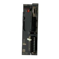
Mitsubishi MR-JE-200B Instruction Manual (294 pages)
MR-JE series
Brand:
Mitsubishi
| Category:
Amplifier
| Size: 3.22 MB
Table of Contents
Safety Instructions
2
Table of Contents
10
Summary
16
Function Block Diagram
17
Servo Amplifier
18
Servo Amplifier Standard Specifications
19
Combinations of Servo Amplifiers, Servo Motors, and Controllers
20
Function List
21
Model Designation
23
Structure
24
Configuration Including Peripheral Equipment
26
Installation Direction and Clearances
29
Keep out Foreign Materials
30
Encoder Cable Stress
31
Inspection Items
33
Parts Having Service Life
34
Restrictions When Using this Product at Altitude Exceeding 1000 M and up to 2000 M above Sea Level
35
Input Power Supply Circuit
37
I/O Signal Connection Example
46
For Source I/O Interface
48
Explanation of Power Supply System
49
Power-On Sequence
50
Wiring CNP1 and CNP2
51
Connectors and Pin Assignment
53
Signal (Device) Explanations
54
Output Device
55
Power Supply
56
Forced Stop Deceleration Function
57
Base Circuit Shut-Off Delay Time Function
58
Vertical Axis Freefall Prevention Function
59
Alarm Occurrence Timing Chart
60
When You Do Not Use the Forced Stop Deceleration Function
61
Hot Line Forced Stop Function
62
Interfaces
68
Detailed Explanation of Interfaces
69
Source I/O Interfaces
70
SSCNET III Cable Connection
71
Servo Motor with an Electromagnetic Brake
73
Timing Chart
75
Grounding
78
Switching Power on for the First Time
81
Wiring Check
82
Surrounding Environment
83
Startup
84
Switch Setting and Display of the Servo Amplifier
85
Scrolling Display
87
Status Display of an Axis
88
Test Operation
90
Test Operation Mode in MR Configurator2
91
Motor-Less Operation in the Controller
93
Parameter List
96
Basic Setting Parameters ([Pr. PA_ _ ])
97
Gain/Filter Setting Parameters ([Pr. PB_ _ ])
98
Extension Setting Parameters ([Pr. PC_ _ ])
99
I/O Setting Parameters ([Pr. PD_ _ ])
101
Extension Setting 2 Parameters ([Pr. PE_ _ ])
102
Extension Setting 3 Parameters ([Pr. PF_ _ ])
103
Detailed List of Parameters
105
Gain/Filter Setting Parameters ([Pr. PB_ _ ])
113
Extension Setting Parameters ([Pr. PC_ _ ])
125
I/O Setting Parameters ([Pr. PD_ _ ])
128
Extension Setting 2 Parameters ([Pr. PE_ _ ])
133
Extension Setting 3 Parameters ([Pr. PF_ _ ])
134
Different Adjustment Methods
136
Adjustment Using MR Configurator2
137
One-Touch Tuning
138
One-Touch Tuning Flowchart
140
Display Transition and Operation Procedure of One-Touch Tuning
142
Caution for One-Touch Tuning
153
Auto Tuning
154
Auto Tuning Mode Basis
155
Adjustment Procedure by Auto Tuning
156
Response Level Setting in Auto Tuning Mode
157
Manual Mode
158
Gain Adjustment Mode
161
Filter Setting
164
Adaptive Filter II
167
Shaft Resonance Suppression Filter
169
Low-Pass Filter
170
Command Notch Filter
174
Gain Switching Function
176
Function Block Diagram
177
Parameter
178
Gain Switching Procedure
181
Tough Drive Function
185
Instantaneous Power Failure Tough Drive Function
187
Model Adaptive Control Disabled
189
Lost Motion Compensation Function
190
Explanation for the Lists
194
Alarm List
195
Warning List
199
Overload Protection Characteristics
206
Power Supply Capacity and Generated Loss
208
Dynamic Brake Characteristics
210
Dynamic Brake Operation
211
Permissible Load to Motor Inertia When the Dynamic Brake Is Used
212
Inrush Current at Power-On
213
Cable/Connector Sets
214
Combinations of Cable/Connector Sets
215
SSCNET III Cable
218
Battery Cable and Junction Battery Cable
220
Regenerative Option
221
Selection of Regenerative Option
222
Parameter Setting
223
Connection of Regenerative Option
224
Dimensions
228
Junction Terminal Block PS7DW-20V14B-F (Recommended)
230
MR Configurator2
231
System Requirements
232
Precautions for Using USB Communication Function
233
Battery
234
MR-BAT6V1SET-A Battery
235
MR-BT6VCASE Battery Case
239
MR-BAT6V1 Battery
245
Selection Example of Wires
246
Molded-Case Circuit Breakers, Fuses, Magnetic Contactors
247
Power Factor Improving AC Reactor
248
Relay (Recommended)
249
Noise Reduction Techniques
250
Earth-Leakage Current Breaker
256
EMC Filter (Recommended)
258
Summary
262
Configuration
263
Battery
264
Using the MR-BT6VCASE Battery Case
265
App. 7 When Turning on or off the Input Power Supply with DC Power Supply
282
App. 8 When Using the Hot Line Forced Stop Function in Combination with MR-J4-_B Servo Amplifier and MR-J4W-_B Servo Amplifier
283
App. 9 Optional Data Monitor Function
284
App. 10 Using the Neutral Point of a 3-Phase 400 V AC Class Power Supply for Inputting a 1-Phase 200 V AC Class Power Supply
285
App. 11 Status of General-Purpose AC Servo Products for Compliance with the China Rohs Directive
287
Advertisement
Advertisement
Related Products
Mitsubishi MR-JE-10B
Mitsubishi MR-JE-20B
Mitsubishi MR-JE-40B
Mitsubishi MR-JE-100B
Mitsubishi MR-JE-70B
Mitsubishi MR-JE-300B
Mitsubishi MR-J4-700A
Mitsubishi MR-J4-200A4
Mitsubishi MR-J4-700A4
Mitsubishi MR-J4-15KA4
Mitsubishi Categories
Air Conditioner
Controller
Projector
Automobile
Engine
More Mitsubishi Manuals
Login
Sign In
OR
Sign in with Facebook
Sign in with Google
Upload manual
Upload from disk
Upload from URL