Sign In
Upload
Manuals
Brands
Mitsubishi Manuals
Engine
L3E
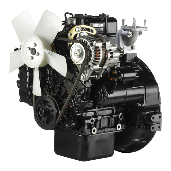
Mitsubishi L3E Industrial Engine Manuals
Manuals and User Guides for Mitsubishi L3E Industrial Engine. We have
5
Mitsubishi L3E Industrial Engine manuals available for free PDF download: Service Manual, Operation & Maintenance Manual, Operation Manual
Mitsubishi L3E Service Manual (254 pages)
Brand:
Mitsubishi
| Category:
Engine
| Size: 6.77 MB
Table of Contents
General Contents
15
Table of Contents
15
General
17
External View
18
External View of L2A, L2C and L2E
18
External View of L3A, L3C and L3E
19
System Flow Diagrams
20
Fuel System - Flow Diagram
20
Lubrication System - Flow Diagram
20
Cooling System - Flow Diagram
21
Inlet and Exhaust System - Flow Diagram
21
Engine Serial Number Location
22
Indication of Engine Model and Total Displacement
22
Specifications
23
Specifications of L2A, L2C and L2E
23
Specifications of L3A, L3C and L3E
27
Tips on Disassembling and Reassembling
31
Disassembling
31
Reassembling
31
Service Data
33
1 Maintenance Service Data
34
Basic Engine
34
Fuel System
37
Cooling System
38
Inlet/Exhaust System
38
Lubrication System
38
Electrical System
39
Basic Engines
42
Fuel System
42
2 List of Tightening Torque
42
Major Bolts and Nuts Tightening Torque
42
Cooling System
43
Electrical System
43
Inlet and Exhaust Systems
43
Lubrication System
43
Standard Bolt and Nut Tightening Torque
44
High-Pressure Fuel Injection Pipe Tightening Torque
45
Standard Eyebolt Tightening Torque
45
Standard Union Nut Tightening Torque
45
Service Tools
47
Determination of Overhaul
51
Determining Overhaul Timing
52
Disassembly of Basic Engine
55
1 Disassembling and Inspecting Cylinder Head and Valve Mechanism
56
Disassembling Rocker Shaft Assembly
57
Removing Rocker Shaft Assembly
57
Removing Cylinder Head Assembly
58
Removing Cylinder Head Bolt
58
Removing Valve Stem Seal
59
Removing Valves and Valve Spring
59
2 Disassembling and Inspecting Flywheel
60
Removing Flywheel
61
Removing Flywheel Housing
61
Removing Oil Seal Case
61
Disassembling and Inspecting Gear Case, Timing Gear and Camshaft
62
3 Disassembling and Inspecting Gear Case, Timing Gears and Camshaft
62
Removing Crankshaft Pulley
63
Removing Gear Pump Housing
63
Removing Tappet
63
Removing Timing Gear Case
63
Removing Governor Shaft and Speed Control Lever
64
Removing Oil Pump
64
Removing PTO Gear
64
Removing Relief Valve
64
Measuring Timing Gear Backlash
65
Removing Idler Gear
65
Removing Camshaft
66
Removing Fuel Injection Pump Camshaft
67
Removing Front Plate
68
4 Disassembling and Inspecting Cylinder Block, Crankshaft, Piston and Oil Pan
69
Removing Oil Pan
70
Removing Oil Screen
70
Removing Connecting Rod Cap
70
Pulling out Piston
71
Removing Piston Ring
71
Removing Piston Pin
71
Measuring Crankshaft End Play
72
Removing Main Bearing Cap
72
Removing Crankshaft
72
Inspection and Repair of Basic Engine
73
1 Inspecting and Repairing Cylinder Head and Valve Mechanism
74
Measuring Clearance between Rocker Arm and Rocker Shaft
74
Measuring Valve Stem Outside Diameter and Valve Guide Inside Diameter
74
Replacing Valve Guide
75
Inspecting Valve Face
76
Refacing Valve Face
76
Measuring Perpendicularity and Free Length of Valve Spring
77
Lapping Valve and Valve Seat
77
Measuring Distortion of the Bottom Surface of the Cylinder Head
78
Measuring Push Rod Runout
78
2 Inspecting and Repairing Flywheel
79
Measuring Flatness of Flywheel
79
Inspecting Ring Gear
79
Replacing Ring Gear
79
Removing Ring Gear
79
Installing Ring Gear
79
3 Inspecting and Repairing Gear Case, Timing Gear and Camshaft
80
Measuring Timing Gear Backlash
80
Measuring Clearance between Idler Gear and Idler Shaft
80
Replacing Idler Shaft
80
Measuring Clearance between
80
Measuring Cam Lift
81
Measuring Cam Height of Fuel Injection Pump Camshaft
81
Inspecting Tappet
82
Measuring Clearance between Tappet and Tappet Guide Hole
82
4 Inspecting and Repairing Cylinder Block, Crankshaft, Piston and Oil Pan
83
Measuring Cylinder Inside Diameter
83
Reboring Cylinder
84
Measuring Piston Outside Diameter
84
Boring Finish Dimension
84
Measuring Piston Ring End Gap
85
Measuring Clearance between Piston Ring Groove and Piston Ring
85
Measuring Piston Pin Bore Diameter and Piston Pin Outside Diameter
86
Measuring Connecting Rod End Play
86
Inspecting Connecting Rod Bend and Twist6-15
87
Measuring Clearance between Connecting Rod Bearing and Crankpin
88
Measuring Clearance between Main Bearing and Crankshaft Journal
89
Measuring Crankshaft Runout
90
Replacing Crankshaft Gear
90
Removing Crankshaft Gear
90
Installing Crankshaft Gear
90
Measuring Distortion Cylinder Block Top Surface
91
Reassembly of Basic Engine
93
1 Reassembling Cylinder Block, Crankshaft, Piston and Oil Pan
94
Installing Main Bearing
94
Installing Crankshaft
94
Installing Main Bearing Cap
95
Inserting Side Seal
95
Installing Main Bearing Cap Bolt
96
Measuring Crankshaft End Play
96
Reassembling Piston and Connecting Rod
97
Installing Piston
98
Installing Piston and Connecting Rod
98
Installing Connecting Rod Cap
99
Installing Oil Screen
100
Installing Oil Pan
100
Reassembling Gear Case, Timing Gears and Camshaft
101
2 Reassembling Gear Case, Timing Gear and Camshaft
101
Installing Front Plate
101
Installing Fuel Injection Pump Camshaft
101
Rotating Crankshaft
101
Installing Camshaft
102
Installing Idler Gear
102
Inspecting and Adjusting Timing Gear after Installation
103
Inspecting Backlash
103
Installing Governor Weights and Sliding Shaft
103
Installing Oil Pump
104
Installing Relief Valve
104
Installing Speed Control Lever and Governor Shaft
104
Installing Crankshaft Pulley
105
Installing PTO Gear
105
Installing Timing Gear Case
105
Installing Gear Pump Housing
106
Installing Tappet
106
3 Reassembling Flywheel
107
Installing Oil Seal Case
107
Installing Flywheel Housing
107
Installing Flywheel
108
4 Reassembling Cylinder Head and Valve Mechanism
109
Cleaning Cylinder Head Bottom Surface
109
Installing Valve Stem Seal
109
Installing Valve Spring
109
Installing Valve Lock
110
Installing Cylinder Head Gasket
110
Installing Cylinder Head Assembly
110
Tightening Cylinder Head Bolts
111
Inserting Push Rod
111
Reassembling Rocker Shaft Assembly
112
Installing Rocker Shaft Assembly
112
Adjusting Valve Clearance
113
Installing Rocker Cover
113
Installing Torque Spring Set
113
Fuel System
115
1 Removing Fuel System
116
Removing Fuel Pipe and Fuel Injection Nozzle
116
Removing Fuel Injection Pipe
117
Removing Fuel Injection Nozzle
117
Removing Fuel Filter
118
Removing Governor
119
Disconnecting Tie Rod from Control Rack
120
Removing Governor Shaft and Speed Control Lever
120
Removing Fuel Injection Pump
121
2 Disassembling, Inspecting and Reassembling Fuel System
122
Disassembling and Inspecting Fuel Injection Nozzles
122
Inspecting and Adjusting Fuel Injection Valve Opening Pressure
123
Inspecting Fuel Spray Pattern of Fuel Injection Nozzle
124
Cleaning and Replacing Faulty Nozzle
124
Reassembling Fuel Injection Nozzles
125
Inspecting Fuel Injection Pump on Engine8-12
126
Disassembling and Inspecting Fuel Injection Pump
126
Removing Swivel Nipple
127
Removing Tappets
127
Removing Plunger
127
Removing Delivery Valve
128
Reassembling Fuel Injection Pump
129
Installing Plunger Barrel
129
Assembling Delivery Valve
130
Assembling Control Sleeve
130
Assembling Plunger
130
Installing Tappet
131
Installing Control Rack
131
Tightening Delivery Valve Holder
132
Inspecting Control Rack for Smooth Operation
132
Installing Lock Plate
132
Installing Swivel Nipple
132
Disassembling and Inspecting Governor Cover
133
Reassembling Governor Cover
133
Disassembling and Inspecting Torque Spring Set
134
Reassembling Torque Spring Set
134
Reassembling Torque Spring Set, Double Spring Type
136
Inspecting Fuel Pump
137
Disassembling, Inspecting and Reassembling Fuel Filter (Cock Switch Type, Push Botton)
138
Disassembling, Inspecting and Reassembling Fuel Filter (Cock Switch Type, Changover)
139
3 Installing Fuel System
140
Installing Fuel Injection Pump
140
Installing Governor
141
Installing Speed Control Lever and Governor Shaft
142
Connecting Tie Rod
142
Installing Torque Spring Set (Single Spring, Double Spring)
143
Installing Torque Set Spring (Double Spring, Two Point Control)
143
Installing Rack Set Screw
144
Installing Fuel Filter
145
Installing Fuel Pipe and Fuel Injection Nozzles
146
Installing Fuel Injection Nozzle
146
Installing Fuel Return Pipe and Fuel Injection Pipe
146
Lubrication System
147
1 Removing Lubrication System
148
Removing Oil Filter, Relief Valve and Oil Pressure Switch
148
Removing Oil Filter
149
Removing Relief Valve
149
Removing Oil Pressure Switch
149
Removing Oil Pump, Oil Pan and Oil Screen9-4
150
Removing Oil Pump
150
2 Disassembling, Inspecting and Reassembling Lubrication System
151
Inspecting Oil Pump
151
Measuring Clearance between Oil Pump Housing Inside Diameter and Oil Pump Outer Gear Outside Diameter
151
Measuring the End Clearance between Oil Pump Outer Gear Width and Oil Pump Housing Depth
151
Inspecting Relief Valve
152
Inspecting Oil Pressure Switch
152
3 Installing Lubrication System
153
Installing Oil Pump, Oil Pan and Oil Screen
153
Installing Oil Pump
153
Installing Oil Filter, Relief Valve and Oil Pressure
154
Installing Oil Pressure Switch
154
Installing Relief Valve
154
Installing Oil Filter
155
Cooling System
157
1 Removing Cooling System
158
Removing Cooling Fan, Fan Pulley, V-Belt, Thermostat, Thermoswitch and Water Pump
158
2 Disassembling, Inspecting and Reassembling Cooling System
159
Disassembling and Inspecting Thermostat10-3
159
Inspecting Thermostat
159
Reassembling Thermostat
160
Inspecting Thermoswitch
160
Inspecting Water Pump
160
Checking Water Pump for Smooth Rotation10-4
160
3 Installing Cooling System
161
Installing Cooling Fan, Fan Pulley, V-Belt, Thermostat, Thermoswitchand Water Pump
161
Inlet and Exhaust Systems
163
1 Removing Inlet and Exhaust Systems
164
Removing Inlet and Exhaust Sysytems
164
Removing Inlet Cover and Exhaust Manifold
164
2 Disassembling, Inspecting and Reassembling Inlet and Exhaust Systems
165
Inspecting Inlet Cover and Exhaust Manifold
165
Measuring Distortion of Inlet and Exhaust Manifold
165
3 Installing Inlet and Exhaust Systems
166
Installing Inlet Cover and Exhaust Manifold
166
Advertisement
Mitsubishi L3E Service Manual (236 pages)
Brand:
Mitsubishi
| Category:
Engine
| Size: 4.93 MB
Table of Contents
Introduction
2
Methods of Indication
3
Abbreviations
4
Safety Cautions
5
Warning Fire and Explosion
5
Check Work Area for Safety
6
Lock out and Tag out
6
Lift Engine
8
Handle LLC
8
Caution Service Battery
9
Caution When Abnormality Occurs
9
Caution Other Cautions
10
Maintain and Inspect Warning Labels
12
General Contents
13
General
14
Outside Drawing
15
Left Side View of Enigne
15
Right Side View of Engine
15
Specifications
20
Maintenance Standards
29
List of Maintenance Standards
30
Engine General
30
Main Unit of Engine
30
List of Tightening Torque
38
Standard Bolt and Nut Tightening Torque
40
Standard Eyebolt Tightening Torque
41
Standard Union Nut Tightening Torque
41
High-Pressure Fuel Injection Pipe Tightening Torque
41
List of Sealant and Lubricant
42
List of Tools
43
Basic Tools
44
Special Tools
45
Overhaul Determination
46
Determining Overhaul Timing
47
Testing Compression Pressure
48
Disassembling Engine Main Parts
49
Disassembling and Inspecting Cylinder Head and Valve Mechanism
50
Removing Rocker Shaft Assembly
51
Disassembling Rocker Shaft Assembly
51
Removing Grooved Pin
51
Removing Cylinder Head Bolt
52
Removing Cylinder Head Assembly
52
Removing Valves and Valve Spring
53
Removing Valve Stern Seal
53
Removing Valve
53
Removing Valve Steam Seal
53
Disassembling and Inspecting Flywheel
54
Removing Flywheel
55
Removing Flywheel Housing
55
Removing Oil Seal Case
55
Detent of Flywheel
55
Disassembling and Inspecting Gear Case, Timing Gears and Camshaft
56
Removing Tappet
57
Removing Gear Pump Housing
57
Removing Crankshaft Pulley
57
Removing Timing Gear Case
57
Removing PTO Gear
58
Removing Oil Pump
58
Removing Governor Shaft and Speed Control Lever
58
Measuring Backlash of Timing Gears
59
Removing Idler Gear
59
Removing Camshaft
60
Removing Fuel Injection Pump Camshaft
61
Removing Front Plate
62
Disassembling and Inspecting Cylinder Block, Crankshaft
63
Removing Oil Pan
64
Removing Oil Screen
64
Removing Connecting Rod Cap
64
Pulling out Piston
65
Removing Piston Ring
65
Removing Piston Pin
65
Measuring Crankshaft End Play
66
Removing Main Bearing Cap
66
Removing Crankshaft
66
Inspecting and Repairing Engine Main Parts
67
Measuring Rocker Arm Inside Diameter and Rocker Shaft Diameter
68
Measuring Valve Stem Outside Diameter
68
Measuring Valve Guide Inside Diameter
68
Replacing Valve Guide
69
Pulling Ou Valve Guide
69
Press Fitting Valve Guide
69
Checking Valve Face
70
Retouching Valve Face
70
Valve-To-Valve Seat Contact Position
70
Measuring Valve Spring Perpendicularity and Free Length
71
Lapping Valve against Valve Seat
71
Measuring Distortion of Cylinder Head Bottom Face
72
Measuring Runout of Pushrod
72
Inspecting and Repairing Flywheel
73
Measuring Flatness of Flywheel
73
Checking Ring Gear
73
Installing Ring Gear
73
Inspecting and Repairing Gear Case, Timing Gears and Camshaft
74
Measuring Backlash of Timing Gear
74
Replacing Idler Shaft
74
Measuring Cam Height
75
Measuring Cam Height of Fuel Injection Pump Camshaft
75
Inspecting Tappet
76
Measuring Cylinder Inside Diameter
77
Measuring Position of Cylinder Inside Diameter
77
Boring Cylinder
78
Measuring Piston Outside Diameter
78
Boring Finish Dimension
78
Measuring Piston Ring End Gap
79
Inspecting Piston Ring Groove
79
Measuring Piston Pin Bore and Piston Pin Diameter
80
Measuring Connection
80
Measuring End Play of Connecting Rod
80
Checking Bend and Twist of Connecting Rods
81
Measurement with Connecting Rod Aligner
81
Measuring Bend of Connecting Rod
81
Measuring Crank Pin Outside Diameter
82
Finish Dimension of Fillet Radius
82
Clearance between Main Bearing and Crank Journal
83
Measuring Crank Journal Outside Diameter
83
Measuring Runout of Crankshaft
84
Replacing Crankshaft Gear
84
Removing Crankshaft Gear
84
Installing Crankshaft Gear
84
Measuring Distortion of Cylinder Block Top Face
85
Reassembling Engine Main Parts
86
Cylinder Block, Crankshaft, Piston and Oil Pan
87
Installing Main Bearing
87
Installing Crankshaft
87
Installing Main Bearing Cap
87
Inserting Side Seal
88
Installing Main Bearing Cap Bolt
88
Reassembling Piston and Connecting Rod
90
Installing Piston Rings
91
Installation Piston and Connecting Rod
91
Installing Connecting Rod Cap
92
Installing Oil Screen
93
Installing Oil Pan
93
Gear Case, Timing Gear and Camshaft
94
Installing Front Plate
94
Turning Engine
94
Installing Fuel Injection Pump Camshaft
94
Installing Camshaft
95
Installing Idler Gear
95
Inspecting Backlash
96
Installing Governor Weights and Sliding Shaft
96
Installing Speed Control Lever and Governor Shaft
97
Installing Relief Valve
97
Installing Oil Pump
97
Installing PTO Gear
98
Installing Timing Gear Case
98
Installing Crankshaft Pulley
98
Installing Gear Pump Housing
99
Installing Tappet
99
Flywheel
100
Installing Oil Seal Case
100
Installing Flywheel Housing
100
Installing Flywheel
101
Tightening Flywheel Bolts
101
Reassembling Cylinder Head and Valve Mechanism
102
Cleaning Cylinder Head Bottom Surface
102
Installing Valve Stem Seal
102
Installing Valve Spring
102
Installing Valve Lock
103
Installing Cylinder Head Gasket
103
Installing Cylinder Head Assembly
103
Tightening Cylinder Head Bolts
104
Inserting Pushord
104
Reassembling Rocker Shaft Assembly
105
Installing Rocker Shaft Assembly
105
Driving in Grooved Pin
105
Adjusting Valve Clearance
106
Installing Rocker Cover
106
Installing Torque Spring Set
106
Fuel System
107
Removing Fuel System
108
Removing Fuel Pipe and Fuel Injection Nozzle
108
Removing Fuel Injection Pipe
109
Removing Fuel Injection Nozzle
109
Removing Fuel Filter
110
Removing Governor
111
Disconnecting Tie Rod from Control Rack
112
Removing Fuel Injection Pump
113
Disassembling and Inspecting Fuel Injection Nozzles
114
Checking Nozzle Opening Pressure
115
Checking Valve Opening Pressure
115
Replacing Fuel Injection Nozzle Tips
115
Checking Fuel Spray Pattern from Fuel Injection Nozzle
116
Cleaning or Replacing When Spray Is Poor
116
Cleaning Nozzle Tip Assembly
116
Reassembling Fuel Injection Nozzles
117
Inspecting Fuel Injection Pump on Engine
118
Disassembling and Inspecting Fuel Injection Pump
118
Removing Swivel Nipple
119
Removing Tappets
119
Removing Plunger
119
Removing Delivery Valve
120
Removing Delivery Valve Holder
120
Removing Delivery Valve Spring
120
Reassembling Fuel Injection Pump
121
Installing Plunger Barrel
121
Assembling Delivery Valve
122
Assembling Control Sleeve
122
Assembling Plunger
122
Installing Control Rack
123
Tightening Delivery Valve Holder
124
Checking Sliding of Control Rack
124
Installing Lock Plate
124
Installing Swivel Nipple
124
Disassembling and Inspecting Governor Cover
125
Reassembling Governor Cover
125
Disassembling and Inspecting Torque Spring Set
126
Reassembling Torque Spring Set
126
Torque Spring Set, Single Spring Type
127
Setting of Torque Spring of Single Spring Type
127
Torque Spring Set, Double Spring Type
128
Inspecting Fuel Pump
129
Inspecting Fuel Filter
130
Installing Fuel System
131
Fuel Injection Pump
131
Governor
132
Installing Governor
132
Connecting Tie Rod
133
Fuel Filter
135
Installing Fuel Pipe an Fuel Injection Nozzles
136
Installing Fuel Injection Nozzle
136
Installing Fuel Return Pipe and Fuel Injection Pipe
136
Lubrication System
137
Removing Lubrication System
138
Removing Oil Filter, Relief Valve and Oil Pressure Switch
138
Removing Oil Filter
139
Removing Relief Valve
139
Removing Oil Pressure Switch
139
Removing Oil Pump, Oil Pan and Oil Screen
140
Inspecting Oil Pump
141
Inspecting Relief Valve
142
Inspecting Oil Pressure Switch
142
Installing Lubrication System
143
Installing Oil Pump, Oil Pan and Oil Screen
143
Installing Oil Pressure Switch
144
Installing Oil Filter
145
Cooling System
146
Removing Cooling System
147
Disassembling and Inspecting Thermostat
148
Inspecting Thermostat
148
Reassembling Thermostat
149
Inspecting Water Pump
149
Checking Water Pump for Smooth Rotation
149
Installing Cooling System
150
Adjusting V-Belt Tension
150
Adjusting Deflection of V-Belt
150
Inlet and Exhaust Systems
151
Removing Inlet and Exhaust Systems
152
Removing Intake Cover and Exhaust Manifold
152
Inspecting Intake Cover and Exhaust Manifold
153
Measuring Distortion of Inlet Cover and Exhaust Manifold
153
Installing Inlet and Exhaust Systems
154
Electrical System
155
Removing Electrical System
157
Removing Starter
157
Checking Alternator Operation
158
Handling Precaution
158
Inspecting Regulated Voltage
159
Checking Output
159
Checking Regulated Voltage
159
Removing Alternator
160
Removing Stop Solenoid
160
Removing Glow Plug
161
Inspecting Pinion Clearance
162
Inspecting Magnet Switch
162
Mitsubishi Heavy Industries L3E Operation & Maintenance Manual (89 pages)
Diesel Engines
Brand:
Mitsubishi Heavy Industries
| Category:
Engine
| Size: 2.95 MB
Table of Contents
Limited Warranty
3
Warranted Parts
4
Warranty Coverage
4
Important Information
9
Table of Contents
12
Chapter 1 BASIC SAFETY PRECAUTIONS Fire and Explosions
18
Keep Flames Away
18
Keep Engine Surrounding Area Tidy and Clean
18
Care for Fuel, Oil and Exhaust Gas Leakage
18
Use Explosion-Proof Lighting Apparatus
18
Prevent Electrical Wires from Short-Circuiting
18
Keep Fire Extinguishers and a First-Aid Kit Handy
18
Stay Clear of All Rotating and Moving Parts
19
Install Protective Covers Around Rotating Parts
19
Check Work Area for Safety
19
Stay Clear of Moving Parts While Engine Is Running
19
Lockout and Tagout
19
Keep Engine Stopped During Servicing
19
Always Restore Engine Turning Tools after Use
19
Changing the Engine Speed Setting Is Prohibited
19
Be Careful of Exhaust Fume Poisoning
20
Operate Engine in a Well-Ventilated Area
20
Be Careful of Falling down
20
Lift Engine Carefully
20
Do Not Climb Onto the Engine
20
Always Prepare Stable Scaffold
20
Protect Ears from Noise
21
Wear Ear Plugs
21
Be Careful of Burns
21
Do Not Touch the Engine During or Immediately after Operation
21
Do Not Open the Radiator Filler Cap When the Engine Is Hot
21
Do Not Touch High Pressure Injection Fuel
21
Refill Coolant Only after the Coolant Temperature Dropped
21
Be Careful When Handling Fuel, Engine Oil or LLC
22
Use Only Specified Fuel, Engine Oil and LLC
22
Handle LLC Carefully
22
Proper Disposal of Waste Oil, LLC and Coolant
22
When Abnormality Occurs
22
Do Not Add Coolant Immediately after a Sudden Stop Due to Overheating
22
Avoid Immediate Restart after Abnormal Stop
22
Avoid Continuous Engine Operation at Low Oil Pressure
22
If Belt Breaks, Stop Engine Immediately
22
Service Battery
23
Handle the Battery Correctly
23
Other Cautions
24
Never Modify Engine
24
Observe Safety Rules at Work Site
24
Work Clothing and Protective Gear
24
Never Break Seals
24
Perform All Specified Pre-Operation Inspections and Periodic Inspections
24
Break-In the Engine
24
Warm up the Engine before Use
24
Never Operate the Engine in an Overloaded Condition
24
Conduct Cooling Operation before Stopping the Engine
25
Protection of the Engine against Water Entry
25
Conduct Proper Maintenance of Air Cleaner
25
Use of Tools Optimum for each Work
25
Avoidance of Prolonged Time of Starter Operation
25
Do Not Turn off the Battery Switch During Operation
25
Cautionary Instructions for Transporting the Engine
25
Chapter 2 NAME of PARTS
26
Engine External Diagrams
26
Equipment and Instrument
28
Starter Switch
28
Preheat Indicator
28
Water Temperature Meter and Thermo Unit
29
Ammeter
29
Hour Meter
29
Stop Solenoid
30
Engine Protection Devices
31
Oil Pressure Switch
31
Thermo Switch
31
Air Cleaner Indicator
31
Chapter 3 OPERATION
32
Preparations for Operation
32
Engine External - Inspect
32
Battery Electrolyte Level - Inspect
32
Fuel Tank Oil Level - Check
33
Engine Oil Level - Check
33
Coolant Level - Check
34
Starting
35
Automatic Glow Plug
35
Manual Glow Plug
35
Table 3-1 Preheat Duration
35
Table 3-2 Preheat Duration (Manual Grow Plug)
35
Warm up Operation
36
Checking Engine Oil Pressure
36
External Inspection During Warm up
36
Operation
37
Cautions When Operating
37
Inspection During Operation
37
Table 3-3 Standard Values at Rated Speed
37
Stopping
38
Inspection after Stopping
38
Chapter 4 FUEL
40
Recommended Fuel
40
Handling Fuel
40
Table 4-1 Recommended Limit and Use Limit of
41
Chapter 5 ENGINE OIL
44
Recommended Engine Oil
44
Selection of Oil Viscosity
44
Handling Engine Oil
44
Engine Oil Performance Requirements
45
Engine Oil Deterioration Mechanisms
45
Definition of Properties of Engine Oil
46
Viscosity
46
Total Base Number
46
Total Acid Number
46
Water Content
46
Flash Point
46
Insoluble
46
Service Limits of Engine Oil
47
Table 5-1 Engine Oil Properties
47
Chapter 6 COOLANT
48
Recommended Water for Coolant
48
Long Life Coolant (LLC)
48
Genuine LLC
48
Glassy - Llc
48
Table 6-1 Water Quality Standards
48
Other Brand Llcs
49
Standard for Other Brand LLC
49
General Demands of LLC
49
LLC Specification
50
Table 6-2 LLC Specification
50
Maintenance of LLC
52
Replacement Intervals of LLC
52
LLC Concentration
52
Table 6-3 Recommended LLC Concentration
52
Importance of LLC
53
Characteristics of LLC Additive and Important Notes
53
Examples of Abnormalities Caused by LLC (Amine Type)
53
Pitting of Iron Parts
53
Corrosion of Aluminum Parts
53
Pitting and Clogging of the Radiator
53
Chapter 7 MAINTENANCE SCHEDULE
54
How to Use the Maintenance Schedule
54
Maintenace Schedule
55
Table 7-1 Maintenace Schedule
55
Advertisement
Mitsubishi L3E Service Manual (155 pages)
L-Series
Brand:
Mitsubishi
| Category:
Engine
| Size: 3.41 MB
Table of Contents
How to Use this Manual
1
ENGLISH Service Manual Mitsubishi L-Series Diesel Engines
4
Table of Contents
5
General
12
Model, Classification and Use
12
1 Engine Model and Engine Number
12
Engine Model Embossment and Engine Number Stamp
12
2 External View
14
Engine L2
14
Engine L3
15
3 Features
16
Aim of Development
16
Features of the New Series
16
4 Specifications
18
5 Maintenance
19
Engine Oil and Oil Filter
19
Retightening the Cylinder Head Bolts
21
Adjusting the Valve Clearance
22
Adjusting the Fan Belt Tension
23
Bleeding Air from the Fuel System
23
Replacing the Fuel Filter
24
Checking and Adjusting Injection Timing
26
Adjusting the Engine Speeds
27
Checking and Adjustment of Nozzles
28
Checking the Compression Pressure
29
6 Troubleshooting
31
Hints on Using the Trouble-Diagnosis Chart
31
Hard Starting
32
Knocking
33
Overheating
34
Black-Smoky Exhaust
35
Unsteady Idling
36
Low Output
37
Engine Main Parts
39
7 General
40
Specifications
40
Special Tools
41
8 Rocker Arms and Rocker Shaft
42
Disassembly
42
Removal and Installation
43
Inspection
43
9 Cylinder Head
44
Disassembly
44
Removal
45
Inspection and Repair
46
Replacement of Valve Guide
46
Service Manual Mitsubishi L-Series Diesel Engines ENGLISH
47
Repair of Valve Seat
47
Installation
48
10 Valves and Valve Springs
49
Disassembly
49
Engine Main Parts
49
Removal
50
Inspection and Repair
50
Installation
51
11 Inlet Manifold and Exhaust Manifold
52
Disassembly
52
Inspection
52
12 Gear Case and Oil Pump
54
Disassembly
54
Removal
55
Inspection
55
Replacement of Front Oil Seal
56
Replacement of Governor Shaft Bushings
56
Inspection of Governor System
57
Disassembly and Reassembly of Governor Levers
57
Installation of Gear Case Assembly
58
13 Timing Gears
59
Disassembly
59
Removal
60
Inspection
60
Installation of Timing Gears
61
14 Camshafts (Valve and Injection Pump)
62
Disassembly
62
Removal of Valve Camshaft
63
Inspection
64
Installation
65
15 Piston and Connection Rod
66
Disassembly
66
Removal
67
Inspection
68
Installation
69
16 Crankshaft
73
Disassembly
73
Removal
74
Inspection
74
Replacement of Crankshaft Rear Oil Seal
76
Installation
77
17 Cylinder Block
78
Disassembly
78
Inspection
79
Reboring of Cylinder
79
Lubrication System
81
General
82
19 Oil Filter and Oil Pressure Switch
83
Removal and Installation
84
Fuel System
85
General
86
Disassembly
88
21 Fuel Injection Pump
89
Inspecting the Injection Pump While Operating the Engine
90
Inspection
91
22 Injection Nozzle
92
Disassembly
93
Inspection
94
Installation
95
Governor System
97
General
98
Disassembly
99
Mitsubishi L3E Operation Manual (44 pages)
SL-Series Diesel Engines
Brand:
Mitsubishi
| Category:
Engine
| Size: 1.22 MB
Table of Contents
Table of Contents
3
Recommendation of Daily Operation Records
2
ENGLISH Operation Manual Mitsubishi SL-Series Diesel Engines
4
1 Safety
5
Preventing Fire and Explosions
5
Prevent Burns
6
Lifting Precautions
7
Exhaust Fumes
7
Prevention of Cuts and Other Injuries
7
Maintenance Precautions
9
Operating Precaution
10
Maintenance Precautions
12
If any Trouble Should Occur
13
2 Important Information
14
Operating the Engine Properly
14
Service the Engine Properly
14
If any Trouble Should Occur
15
3 Specifications
16
4 Nomenclature
17
Engine S3L/S3L2
17
Engine S3L-T/S3L2-T
18
Engine S4L/S4L2
19
Engine S4L-T/S4L2-T
20
5 Operation
21
Pre-Start Inspection
21
5.1.1 Walk-Around Inspection
21
5.1.2 Check Engine Oil Level
21
[Pre-Start Inspection] Check Fuel Level
21
Check Coolant Level
21
Starting the Engine
22
Warming up the Engine
23
Starting the Load
23
Stopping the Engine
23
Maintenance 6 Maintenance
25
6 Maintenance
25
Every 50 Service Hours
26
Drain Water and Sediment from the Fuel Tank and Water Separator
26
Check the Battery Electrolyte Level and Specific Gravity
26
Every 100 Service Hours
27
Every 250 Service Hours or Once a Year
27
Change Engine Oil See SPECIFICATIONS (Page 16)
27
Every 100 Service Clean Fuel Filter Element after Cleaning, Prime (Page 31)
27
Hours Clean Radiator Fins
27
Every 250 Service Change Engine Oil See SPECIFICATIONS (Page 16)
27
Every 500 Service Hours
28
Change Fuel Filter Element after Changing, Prime (Page 31)
28
Every 500 Service
28
Check and Adjust Fan Belt Deflection: 13 MM (0.5 In.)
28
Every 1000 Service Hours
29
Every 2 Years
29
Every 1000 Service Check Starter
29
Hours Check Alternator
29
Every 2 Years Change Coolant See SPECIFICATIONS (Page 16)
29
Operation Manual Mitsubishi SL-Series Diesel Engines ENGLISH
29
When Required
31
7 Fuel Specifications
33
Recommended Types of Fuels
33
Caring for the Diesel Fuel Tank
33
Caring for the Fuel Supply
33
8 Lubricant Specifications
34
Recommended Types of Engine Oils
34
Recommended Oil Viscosities
34
Limiting Requirements for Engine Oils
35
9 Coolant and Antifreeze Specifications
36
Coolant Specifications
36
Recommended Types of Llc's (Long Life Coolant)
36
Operation Manual Mitsubishi SL-Series Diesel Engines ENGLISH
37
How to Use Non-Amine Type LLC
37
Why LLC
37
How LLC Works
37
Practical Reported Cases of Circuit Trouble for Which Additive Is Blamed
38
10 Storage
39
Storage of the Engine in a Non-Operational Condition
39
Storage of the Engine in an Operational Condition
39
11 Troubleshooting
40
11.1 General
40
11.2 Problems
41
12 Additional Information
44
Advertisement
Related Products
Mitsubishi L2A
Mitsubishi L2C
Mitsubishi L3C
Mitsubishi L2E
Mitsubishi L3A
Mitsubishi LaserVue L65-A90
Mitsubishi UNISEN LT-40151
Mitsubishi LVP-SD10U
Mitsubishi LANCER 2012
Mitsubishi LT-5V
Mitsubishi Categories
Air Conditioner
Controller
Projector
Automobile
Engine
More Mitsubishi Manuals
Login
Sign In
OR
Sign in with Facebook
Sign in with Google
Upload manual
Upload from disk
Upload from URL