Sign In
Upload
Manuals
Brands
Mitsubishi Heavy Industries Manuals
Air Conditioner
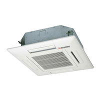
FDEN Series
Mitsubishi Heavy Industries FDEN Series Manuals
Manuals and User Guides for Mitsubishi Heavy Industries FDEN Series. We have
1
Mitsubishi Heavy Industries FDEN Series manual available for free PDF download: Technical Manual
Mitsubishi Heavy Industries FDEN Series Technical Manual (521 pages)
HYPER INVERTER PACKAGED AIR-CONDITIONERS FDT, FDF, FDTC, FDEN, SRK, FDC, FDUM Series
Brand:
Mitsubishi Heavy Industries
| Category:
Air Conditioner
| Size: 28.87 MB
Table of Contents
V Multi System
1
Table of Contents
3
Specifications
7
Ceiling Cassette-4Way Compact Type (FDTC)
26
Ceiling Suspended Type (FDEN)
36
Duct Connected-High Static Pressure Type (FDU)
55
Duct Connected-Low/Middle Static Pressure Type (FDUM)
62
Floor Standing Type (FDF)
79
Wall Mounted Type (SRK)
88
Ceiling Cassette-4Way Type (FDT)
94
Exterior Dimensions
94
Outdoor Units
108
Remote Controller (Option Parts)
111
Electrical Wiring
114
Ceiling Suspended Type (FDEN)
116
Duct Connected-High Static Pressure Type (FDU)
118
Duct Connected-Low / Middle Static Pressure Type (FDUM)
120
Floor Standing Type (FDF)
123
Wall Mounted Type (SRK)
124
Outdoor Units
125
Noise Level
129
Characteristics of Fan
135
Temperature and Velocity Distribution
139
Piping System
148
Preset Point of the Protective Devices
150
Range of Usage & Limitations
151
Operating Temperature Range
152
Capacity Tables
155
Ceiling Cassette-4Way Compact Type (FDTC)
165
Ceiling Suspended Type (FDEN)
170
Pac-T
174
Duct Connected-High Static Pressure Type (FDU)
180
Duct Connected-Low/Middle Static Pressure Type (FDUM)
182
Floor Standing Type (FDF)
191
Wall Mounted Type (SRK)
196
Selection Chart
155
Correction of Cooling and Heating Capacity in Relation to Air Flow Rate Control (Fan Speed)
202
How to Obtain the Cooling and Heating Capacity
203
Piping Length Limitations
203
Application Data
204
Installation of Indoor Unit
204
Before Installation
205
Preparation before Installation
205
Selection of Installation Location for the Indoor Unit
205
Drain Pipe
206
Refrigerant Pipe
206
Check List after Installation
207
How to Check the Dirt of Drain Pan
207
Panel Installation
207
Wiring-Out Position and Wiring Connection
207
Checking the Indoor Unit Installation Position
208
Panel Installation Manual
208
Removing a Corner Panel
208
Removing the Air Return Grille
208
Attaching a Corner Panel
209
Attaching the Air Return Grille
209
How to Set the Airflow Direction
209
Outdoor Air (Oa) Intake for Fdt
210
Selection of Booster Fan
210
Ceiling Cassette-4Way Compact Type (FDTC)
211
Safety Precautions
211
Drain Pipe
213
Refrigerant Pipe
213
Panel Installation
214
How to Set the Airflow Direction
216
Ceiling Suspended Type (FDEN)
217
Remote Controller
218
Duct Connected-High Static Pressure Type (FDU)
221
Duct Connected-Low/Middle Static Pressure Type (FDUM)
225
Replacement Procedure of the Fan Unit
230
Floor Standing Type (FDF)
231
Effective Range of Cool/Hot Wind (Reference)
239
Cable Connection for a V Multi Configuration Installation
240
Cable Connection for Single Unit Installation
240
Electric Wiring Work Installation
240
Confirming Method of Indoor Units
241
Control Plural Indoor Units by a Single Remote Controller
241
Installation and Wiring of Remote Controller
241
The Method of Trial Cooling Operation
241
The Functional Setting
242
Control Mode Switching
243
Function of CNT Connector of Indoor Printed Circuit Board
243
Troubleshooting
243
Electric Wiring Work Instruction
244
FDUM Series
244
FDF Series
247
Installation of Wired Remote Controller (Option)
251
Flow of Function Setting
254
Installation Manual
257
Safety Precautions
258
Accessories & Prepare on Site
260
Cautions for Selecting Installation Place
260
Remote Control Installation Procedure
260
Installation Procedure
261
Main-Sub Setting for Use of Two or more R/Cs
263
Main/Sub Setting When more than One Remote Control Are Used
263
Note: Combination of R/C and Indoor Unit
264
Note: Connection to Personal Computer
264
Note: Initializing of Password
264
Branching Pipe Set Specifications
288
Instructions for Branching Pipe Set (DIS-WA1,WB1,TA1,TB1)
288
Pipe Connecting Procedure
288
Heat Insulation Work
290
Outline of Operation Control by Microcomputer
291
Wired Remote Controller
291
Operation Section
293
Wireless Remote Controller
293
CPU Reset
294
Operation Control Function by the Wired Remote Controller
294
Parts Layout on Remote Controller PCB
294
Power Failure Compensation Function
294
Switching Sequence of the Operation Mode Switches of Remote Controller
295
Auto Operation
297
Dehumidifying Operation
298
Operations of Functional Items During Cooling/Heating
298
Timer Operation
299
Combination of Patterns Which Can be Set for the Timer Operations
299
Ending Condition
300
Hot Keep
300
Hot Start (Cold Draft Prevention at Heating)
300
Remote Controller Display During the Operation Stop
300
Fan Control During Heating Thermostat off
301
Thermostat Operation
301
Operation Control Function by the Indoor Controller
297
Compressor Inching Prevention Control
302
Drain Motor (DM) Control
302
Cooling, Dehumidifying Frost Protection
303
Operation Check/Drain Pump Test Run Operation Mode
303
Selection of Indoor Fan Speed
303
Anomalous Fan Motor
304
Heating Overload Protection
304
Plural Unit Control
304
Abnormal Temperature Thermistor Wire/Short-Circuit Detection
305
External Input/Output Control
305
High Ceiling Control
305
Priority Order for Combinations of Cnt and Cnta Input
305
In Case of “Level Input” Setting (Factory Default)
306
In Case of “Pulse Input” Setting (Local Setting)
306
Output for External Control
306
Remote Operation Input
306
Operation Permission/Prohibition
307
Selection of Cooling/Heating External Input Function
308
Drain Pump Control
302
Filter Sign
302
Fan Control at Heating Startup
309
High Power Operation
309
Return Air Temperature Compensation
309
Room Temperature Detection Temperature Compensation During Heating
309
Auto Fan Speed Control
310
Fan Circulator Operation
310
IU Overload Alarm
310
The Operation Judgment Is Executed Every 5 Minutes ( RC EX1A Only)
310
Unit ON/OFF Button
311
Auto Restart Function
311
Auto Swing Control
311
Outline of Heating or Cooling Operation
312
Timer Operation
312
Indoor Fan Motor Protection
313
Serial Signal Transmission Error Protection
313
Filter Sign
314
O P Eration Control Function by the Outdoor Controller
315
Cooling Overload Protective Control
316
Cooling High Pressure Control
316
Cooling Low Outdoor Temperature Protective Control
316
Heating High Pressure Control
317
Heating Overload Protective Control
317
Indoor Heat Exchanger Temperature
317
Compressor Overheat Protection
318
Heating Low Outdoor Temperature Protective Control
318
Outdoor Unit Side
318
Current Safe
319
Current Cut
319
Outdoor Unit Failure
319
Rotor Lock
319
Refrigeration Cycle System Protection
320
Determination of Compressor Speed (Frequency)
321
Required Frequency
321
Compressor Start Control
321
Compressor Soft Start Control
322
Outdoor Unit Fan Control
323
Outdoor Unit Fan Tap and Fan Motor Speed
323
Fan Tap Control During Cooling/Defumidifying Operation
323
Fan Tap Control During Heating Operation
323
Outdoor Unit Fan Control by Power Transistor Radiator Fin Temperature
324
Caution at the Outdoor Unit Fan Start Control (3 Phase Model Only)
324
Snow Protection Fan Control
324
Defrosting
325
Defrosting End Conditions
325
Switching of Defrosting Control with SW3-1
326
Compressor Discharge Pipe Temperature Protection
326
Cooling High Pressure Protection
326
Heating High Pressure Protection
327
Anomaly Detection Control by the High Pressure Switch
327
Low Pressure Control
327
Compressor Pressure Ratio Protection Control
327
Over-Current Protection Current Safe Controls I, II
328
Power Transistor Temperature Protection
328
Anomalous Power Transistor Current
328
Anti-Frost Control by the Compressor Frequency Control
328
Dewing Prevention Control
329
Refrigerant Quantity Shortage Protection
329
Fan Motor Error
329
Anomalous Stop by the Compressor Start Stop
329
Silent Mode
330
Test Run
330
Pump-Down Control
330
Control Ending Conditions
330
Base Heater ON/OFF Output Control
331
Base Heater on Conditions
331
Base Heater off Conditions
331
Maintenance Data
332
Diagnosing of Microcomputer Circuit
332
Check Indicator Table
332
Display Sequence of Error Codes or Inspection Indicator Lamps
337
Occurrence of One Kind of Error
337
Occurrence of Plural Kinds of Error
337
Error Detecting Timing
337
Error Log and Reset
338
Resetting the Error Log
338
Instruction of How to Replace Indoor Control PCB
338
Control PCB
339
Replace the PCB
339
Power PCB
340
Replace and Set up the PCB According to this Instruction
344
Items to Check before Troubleshooting
348
Troubleshooting Procedure (if the Air Conditioner Does Not Run at All)
348
Troubleshooting at the Outdoor Unit
349
Reset of Power Supply
349
Module of Part to be Replaced for Outdoor Unit Controller
349
Replacement Procedure of Outdoor Control PCB
349
Position of Terminal
350
Outdoor Inverter PCB Replacement Procedure
352
DIP Switch Setting List (Outdoor Unit)
355
Check of Anomalous Operation Data with the Remote Controller
356
Power Transistor Module (Including Driver PCB) Inspection Procedure
358
Power Transistor Module Terminal Short Circuit Check Procedure
358
Inverter Checker for Diagnosis of Inverter Output
359
Outdoor Unit Controller Failure Diagnosis Circuit Diagram
360
Troubleshooting Flow
364
List of Troubles
364
Operates but Does Not Cool
366
Troubleshooting
366
Operates but Does Not Heat
367
Earth Leakage Breaker Activated
368
Excessive Noise/Vibration (2/3)
369
Excessive Noise/Vibration (3/3)
370
Louver Motor Failure
372
Power Supply System Error (Power Supply to Indoor Control PCB)
373
Power Supply System Error (Power Supply to Remote Controller)
374
INSPECT I/U (When 1 or 2 Remote Controllers Are Connected)
375
INSPECT I/U (Connection of 3 Units or more Remote Controllers)
376
Communication Error at Initial Operation (Models SRC40-60 Only)
377
Wait
377
No Display
383
Remote Controller Communication Circuit Error
384
Communication Error During Operation
385
Indoor Heat Exchanger Temperature Thermistor Anomaly
386
Return Air Temperature Thermistor Anomaly
387
Heating Overload Operation
388
Drain Trouble
389
Excessive Number of Connected Indoor Units (more than 17 Units)
390
Communication Error between Master and Slave Indoor Units
391
Indoor Fan Motor Anomaly
392
Address Setting Error of Moster and Slave Indoor Unit
393
Indoor Unit Operation Check, Drain Motor Check Setting Error
394
Indoor Fan Motor Rotation Speed Anomaly
395
Defective Panel Switch Operation (FDT)
396
Remote Controller Temperature Thermistor Anomaly
397
Cooling Overload Operation (Models SRC40-60 Only)
398
Discharge Pipe Temperature Error
400
Outdoor Heat Exchanger Temperature Thermistor Anomaly
401
Outdoor Air Temperature Thermistor Anomaly
402
Discharge Pipe Temperature Thermistor Anomaly
403
Power Transistor Overheat
405
Current Cut 405
406
Communication Error between Inverter PCB and Outdoor Control PCB
408
Active Filter Voltage Error
409
Inverter PCB A/F Module Anomaly
410
Outdoor Fan Motor Anomaly (Models SRC40-60 Only)
411
Low Pressure Error or Low Pressure Sensor Anomaly
413
Power Transistor Anomaly (Models SRC40-60 Only)
415
Inverter and Fan Motor Anomaly
416
Suction Pipe Temperature Thermistor Anomaly
417
Low Pressure Sensor Anomaly
418
Insufficient Refrigerant Amount of Detection of Service Valve Closure
419
Current Safe Stop (Models SRC40-60 Only)
421
Compressor Startup Failure (Models SRC40-60 Only)
422
Compressor Rotor Lock Error
425
General Information
469
V Multi System
469
Table of Models
470
Table of System Combinations
470
Specifications
471
Indoor Units
471
(A) Ceiling Cassette-4Way Type (FDT)
471
(B) Ceiling Suspended Type (FDEN)
475
Outdoor Units
479
Operation Chart
486
Exterior Dimensions
489
Electrical Wiring
489
Noise Level
489
Temperature and Velocity Distribution
489
Piping System
489
Range of Usage & Limitations
489
Selection Chart
489
Application Data
489
Outline of Operation Control by Microcomputer
489
Maintenance Data
489
Option Parts
490
Wireless Kit
491
FDT Series (RCN-T-36W-E)
491
How to Insert Batteries
492
Backup Button
492
FDTC Series (RCN-TC-24W-ER)
493
FDEN Series (RCN-E1R)
495
FDU, FDUM, FDF Series (RCN-KIT3-E)
499
Simple Wired Remote Conroller (Rch-E3)
501
Base Heater Kit (Cw-H-E)
507
Interface Kit (Sc-Bikn-E)
513
Cable Connection for SRK Twin / Triple Installation
517
Super Link E Board (Sc-Adna-E)
518
Advertisement
Advertisement
Related Products
Mitsubishi Heavy Industries FDENVA602HENP2R
Mitsubishi Heavy Industries FDENA501R
Mitsubishi Heavy Industries FDEN140VNTV
Mitsubishi Heavy Industries FDEN50V
Mitsubishi Heavy Industries FDEN100VF
Mitsubishi Heavy Industries FDEN140VSXPVF
MHI FDENVA201HEN
Mitsubishi Heavy Industries FDEN100VSVF1
Mitsubishi Heavy Industries FDEN250VSPVF
Mitsubishi Heavy Industries FDEN140VSTVF
Mitsubishi Heavy Industries Categories
Air Conditioner
Remote Control
Heat Pump
Engine
Control Systems
More Mitsubishi Heavy Industries Manuals
Login
Sign In
OR
Sign in with Facebook
Sign in with Google
Upload manual
Upload from disk
Upload from URL