Sign In
Upload
Manuals
Brands
Mitsubishi Electric Manuals
Controller
CR800-05VD
Mitsubishi Electric CR800-05VD Manuals
Manuals and User Guides for Mitsubishi Electric CR800-05VD. We have
2
Mitsubishi Electric CR800-05VD manuals available for free PDF download: Standard Specifications Manual, Instruction Manual
Mitsubishi Electric CR800-05VD Standard Specifications Manual (140 pages)
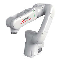
For Industrial Robot RV-5AS-D
Brand:
Mitsubishi Electric
| Category:
Controller
| Size: 15.52 MB
Table of Contents
Table of Contents
6
General Configuration
9
Structural Equipment
9
Standard Structural Equipment
9
Options
9
Maintenance Parts
9
Model Type Name of Robot
10
How to Identify the Robot Model
10
Contents of the Structural Equipment
11
Robot Arm
11
Controller
12
Function Extension Device
13
Minimum Equipment Required to Operate the Robot
14
Contents of the Option Equipment
16
List of the Robot Arm Option Equipment
16
List of the Controller Option Equipment and Special Specification
16
Function Extension Device
17
Recommended Vision Sensors
17
Recommended Hands
18
Robot Arm
20
Standard Specifications
20
Basic Specifications
20
The Counter-Force Applied to the Installation Surface
21
Definition of Specifications
22
Pose Repeatability
22
Rated Load (Mass Capacity)
23
Relationships Among Mass Capacity, Speed, and Acceleration/Deceleration Speed
24
Setting Hand and Workpiece Conditions
24
Vibrations at the Tip of the Arm During Low-Speed Operation of the Robot
24
Collision Detection
25
Protection Specifications
25
Types of Protection Specifications
25
About the Use with the Bad Environment
26
Names of each Part of the Robot
27
Operation Buttons
28
Status Indicator LED
29
Outside Dimension • Operating Range Diagram
31
Outside Dimensions of Machine Cables
34
Tooling
35
Wiring and Piping for Hand
35
Internal Wiring and Piping
37
Internal Pneumatic Plumbing
37
Internal Wiring of the Hand I/O Cables
37
Ethernet Cable and Force Sensor Wiring
37
Wiring and Piping System Diagram for Hand
38
Electrical Specifications of Hand Input/Output
39
Air Supply Circuit Example for the Hand
40
About the Installation of Tooling Wiring and Piping
40
Options
41
Machine Cable (Replacement)
42
Solenoid Valve Set
43
2-Piece Force Sensor Conversion Cable Set
45
Vision Sensor Mounting Bracket
46
About Overhaul
47
Maintenance Parts
48
Controller
49
Standard Specifications
49
Basic Specifications
49
CR800-05VD Controller
49
Safety Extension Unit
51
Protection Specifications and Operating Supply
53
Protection Specifications
53
Operating Supply
53
Names of each Part
54
CR800-05VD Controller
54
Safety Extension Unit
56
Outside Dimensions/Installation Dimensions
57
Outside Dimensions
57
CR800-05VD Controller
57
Safety Extension Unit
60
Installation Dimensions
61
External Input/Output
63
Types
63
Dedicated Input/Output
64
Emergency Stop Input and Output Etc
67
Connection of the External Emergency Stop and Mode Selector Switch
67
Special Stop Input (SKIP)
71
Door Switch Function
72
Mode Selector Switch Function
72
Automatic Operation/Jog Operation/Brake Release and Necessary Switch Settings
73
Options
75
Teaching Pendant (T/B)
76
High Efficient Teaching Pendant (T/B)
79
MELSOFT RT Toolbox3/Melsoft RT Toolbox3 Mini
81
MELSOFT RT Visualbox
83
Parallel I/O Interface
85
External I/O Cable
90
CC-Link Interface
92
SD Memory Card
95
Easy-Setup Kit
96
Maintenance Parts
98
Software
99
List of Commands
99
Instruction Manual
100
The Details of each Instruction Manuals
100
Safety
101
Self-Diagnosis Stop Functions
101
External I/O Signals that Can be Used for Preventative Safety Measures
102
Examples of Safety Measures
103
External Emergency Stop Connection [Supplementary Explanation]
110
Working Environment
111
Power Supply
111
Noise
111
Temperature and Humidity
111
Vibration
111
Installation Environment
111
Precautions for Handling
111
7Appendix
113
Appendix 1: Inertia Calculation Method
113
Load Moment Calculation Example (for J5 Axis with Flange Facing Downwards)
113
Load Inertia Calculation Example (for J6 Axis)
113
Appendix 2: Classification of External I/O Functions
114
Appendix 3: Safety Diagnosis Function (Test Pulse Diagnosis)
115
Appendix 4: Safety Block Diagram
116
Appendix 5: Connections of Recommended Hands, Recommended Vision Sensors and the Force Sensor
118
Hand: HRC-03-099455 (Manufactured by Zimmer Group)
122
Hand: KIT-ASSISTA-G (Manufactured by GIMATIC)
126
Hand: ROB-SET ECBPM ASSISTA (Manufactured by SCHMALZ)
131
Appendix 6: Declaration of Conformity
135
Appendix 7: Specifications Discussion Material
138
Advertisement
Mitsubishi Electric CR800-05VD Instruction Manual (72 pages)
Industrial Robot
Brand:
Mitsubishi Electric
| Category:
Controller
| Size: 6.54 MB
Table of Contents
Table of Contents
8
1 Before Starting Use
10
Using the Instruction Manuals
10
The Details of each Instruction Manuals
10
Symbols Used in this Manual
11
2 Unpacking to Installation
12
Confirming the Products
12
Installation
13
Unpacking Procedures
13
Transportation Procedures
13
Installation Procedures
14
CR800-05VD Controller
14
Safety Extension Unit
16
Connection
17
Connecting the Power Cable and the Grounding Cable
17
Emergency Stop Input and Output Etc
18
Connecting the External Emergency Stop and Mode Selector Switch
19
Examples of Safety Measures
25
External Emergency Stop Connection [Supplementary Explanation]
32
Connecting to the Robot Arm
33
Connecting a Machine Cable
33
Removing a Machine Cable
33
Connecting the Safety Extension Unit to the Controller
34
Equipment Supplied by Customer
34
Connection Method
34
Connectors and Pin Assignment
35
Electrical Specifications
38
Station Number
43
3 Installing the Option Devices
44
Installing/Removing the Option Card
44
Installing the Option Card
44
Removing the Option Card
45
Installing and Connecting the Easy-Setup Kit
46
Installing the Easy-Setup Kit
46
Installing the Earth Leakage Breaker / Safety Extension Unit Power Supply Box
46
Installing the EMG / Mode Selector Switch Box
46
Installing the Safety Extension Unit
47
Connecting the Easy-Setup Kit
47
Connecting the Power Supply and Grounding Wire to the Safety Extension Unit
47
Connecting the Robot Controller and the Earth Leakage Breaker / Safety Extension Unit Power Supply Box
48
Connecting SDIO Cables to the Safety Extension Unit
49
Connecting the Safety Extension Unit to the Robot Controller
50
Connecting the EMG / Mode Selector Switch Box to the Robot Controller
51
4 Basic Operations
52
Handling the Controller
53
Names of each Parts
53
CR800-05VD Controller
53
Safety Extension Unit
55
Handling the T/B
56
Installing and Removing the T/B
56
Installing the T/B
56
Removing the T/B
56
Functions of each Key
57
Turning the Power on and off
58
Turning the Control Power on
58
Input the Serial Number
59
Setting the Serial Number Using RT Visualbox
59
Setting the Serial Number Using the Teaching Pendant
63
Shutting off the Control Power
64
Changing the Power Supply Voltage Settings
65
5 Maintenance and Inspection
66
Maintenance and Inspection Interval
66
Inspection Items
67
Daily Inspection Items
67
Periodic Inspections
67
Maintenance and Inspection Procedures
68
The Check of the Filter, Cleaning, Exchange
68
Maintenance Parts
69
Advertisement
Related Products
Mitsubishi Electric CR800 Series
Mitsubishi Electric CR800-D Series
Mitsubishi Electric CR800-R Series
Mitsubishi Electric CR800-Q Series
Mitsubishi Electric CR860-R
Mitsubishi Electric CR751-D Series
Mitsubishi Electric CR751-Q Series
Mitsubishi Electric CR750 Series
Mitsubishi Electric CR760-Q
Mitsubishi Electric CR751 Series
Mitsubishi Electric Categories
Air Conditioner
Controller
Projector
Inverter
Heat Pump
More Mitsubishi Electric Manuals
Login
Sign In
OR
Sign in with Facebook
Sign in with Google
Upload manual
Upload from disk
Upload from URL