Sign In
Upload
Manuals
Brands
Mitsubishi Electric Manuals
Control Systems
CNC 700 Series
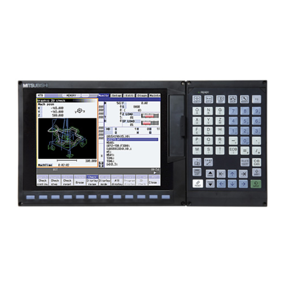
Mitsubishi Electric CNC 700 Series Manuals
Manuals and User Guides for Mitsubishi Electric CNC 700 Series. We have
1
Mitsubishi Electric CNC 700 Series manual available for free PDF download: Connection Manual
Mitsubishi Electric CNC 700 Series Connection Manual (293 pages)
Brand:
Mitsubishi Electric
| Category:
Control Systems
| Size: 5.19 MB
Table of Contents
Table of Contents
13
Introduction
20
System Configuration
21
System Basic Configuration Drawing
21
General Connection Diagram
22
Display Unit: FCU7-DA201-11/FCU7-DA211-11
22
Display Unit
23
Fcu7-Da315-11/Fcu7-Da415-11/Fcu7-Da445-11/Fcu7-Da335-11/Fcu7-Da435-11
23
List of Configuration Units
24
Control Unit: FCU7-MU001/FCU7-MU002/FCU7-MU011/FCU7-MA011
24
Fcu7-Da415/Fcu7-Da445/Fcu7-Da335/Fcu7-Da435
25
Operation Panel I/O Unit: FCU7-DX670/FCU7-DX671/FCU7-DX770/FCU7-DX771
26
Keyboard Unit : FCU7-KB021/FCU7-KB022/FCU7-KB041
26
Remote I/O Unit: FCUA-DX100/DX110/DX120/DX140/DX101/DX111/DX121/DX141
27
Scan I/O: HR357/HR347
27
Card-Sized I/O Card: HR361/HR371/HR381/HR383
27
Extended I/O Card: QY231
28
Front IC Card Interface: FCU7-EP102-1 (Option)
28
Hard Disk Unit: FCU7-HD001-1
28
Floppy Disk Unit: FCU7-FD221
28
Expansion Unit: FCU7-EX891
29
Expansion Card
29
External Power Supply Unit: PD25/PD27
29
General Specifications (Environment Conditions)
30
Environment Conditions in Operation Box
30
Environment Specifications in Electric Cabinet
31
Remote I/O Unit
32
Servo / Spindle
32
Heat Radiation Countermeasures
33
Noise Countermeasures
36
Connection of FG (Frame Ground)
36
Shield Clamping of Cables
37
Connecting Spark Killers
37
Outline Drawing
38
Control Unit
38
Display Unit
43
FCU7-DA201 (8.4-Type)
43
FCU7-DA211 / FCU7-DA315 / FCU7-DA415 / FCU7-DA445 (10.4-Type)
44
FCU7-DA335 / FCU7-DA435 (15-Type)
46
FCU7-DA201 (8.4-Type) / FCU7-DA211 (10.4-Type) Rear View
48
FCU7-DA315 / FCU7-DA415 / FCU7-DA445 / FCU7-DA335 / FCU7-DA435 Rear View
49
FCU7-EP102 (Front IC Card I/F Unit)
50
Operation Panel I/O Unit
51
FCU7-DX670 / FCU7-DX671 / FCU7-DX770 / FCU7-DX771 Outline Drawing
51
Keyboard Unit
52
FCU7-KB021 / FCU7-KB022 (ONG Layout)
52
FCU7-KB041 (ABC Layout)
52
Hard Disk Unit
53
Fcu7-Hd001-1
53
Floppy Disk Unit
54
Fcu7-Fd221-1
54
Card-Sized I/O Card
55
Hr361 / Hr371 / Hr381 / Hr383
55
Remote I/O Unit Outline
57
Fcua-Dx100 / Fcua-Dx110 / Fcua-Dx120 / Fcua-Dx140 / Fcua-Dx101 / Fcua-Dx111 / Fcua-Dx121 / Fcua-Dx141
57
Grounding Plate and Clamp Fitting
58
Panel Cut Dimension Drawing / Installation Dimension Drawing
59
Control Unit
59
Display Unit
60
FCU7-DA201 (8.4-Type)
60
FCU7-DA211 / FCU7-DA315 / FCU7-DA415 / FCU7-DA445 (10.4-Type)
61
FCU7-DA335 / FCU7-DA435 (15-Type)
62
Operation Panel I/O Unit
63
Fcu7-Dx670 / Fcu7-Dx671 / Fcu7-Dx770 / Fcu7-Dx771
63
Keyboard Unit
64
FCU7-KB021 / FCU7-KB022 (ONG Layout)
64
FCU7-KB041 (ABC Layout)
65
Hard Disk Unit
66
Fcu7-Hd001
66
Mounting on a Keyboard Unit
67
External Power Supply Unit
68
Pd25
68
Pd27
69
Mounting Direction and Clearance
69
Remote I/O Unit
70
Fcua-Dx100 / Fcua-Dx110 / Fcua-Dx120 / Fcua-Dx140 / Fcua-Dx101 / Fcua-Dx111 / Fcua-Dx121 / Fcua-Dx141
70
Manual Pulse Generator
71
Ufo-01-2Z9
71
Hd60
72
Synchronous Feed Encoder
73
Ose-1024-3-15-68
73
F Installation Plate
74
Connections of Control Unit
75
Control Unit Connection System Drawing
75
Connecting with Power Supply
76
When Using General-Purpose 24VDC Stabilized Power Supply
76
When Using PD25/PD27 Power Supply Unit
77
Connecting with Operation Panel I/O Unit
78
Connecting with Remote I/O Unit
79
Connecting with Scan I/O Card and Card-Sized I/O Card
79
Connecting with Optical Communication Servo Drive Unit
80
Connecting with Auxiliary Axis Servo Drive Unit: MR-J2-CT
82
Connecting with Expansion Unit
83
Connecting with I/O Device Using PROFIBUS-DP
83
Expanding Optical Servo Communication I/F
84
Connecting I/O Devices Via CC-Link
85
Connecting with RS-232C Device
87
Connecting with Skip Signal (Sensor)
89
Connecting with Synchronous Feed Encoder/Manual Pulse Generator
91
Connections of Emergency Stop Signal
92
Connecting with Safety Observing I/O Device: SDIO Connector
94
Connections of Operation Panel I/O Unit
97
Operation Panel I/O Unit Connection System Drawing
98
Connecting with Power Supply
99
Connecting with Display Unit
100
Connecting with Keyboard Unit
101
Connections of Emergency Stop Signal
102
Connecting with Manual Pulse Generator
104
Connecting with 12V Manual Pulse Generator (Maximum Cable Length: 50M)
104
Connecting with 5V Manual Pulse Generator (Maximum Cable Length: 20M)
105
Connecting with Remote I/O Unit
106
Connecting with Scan I/O Card and Card-Sized I/O Card
106
Connecting with Machine Operation Panel
107
Wiring the Input Side DI Connector (CG31/CG33)
107
Wiring the Output Side DO Connector (CG32/CG34)
107
Outline of Digital Signal Input Circuit
108
Outline of Digital Signal Output Circuit
110
Wiring for Sink Type Output (FCU7-DX670/DX770)
111
Wiring for Source Type Output (FCU7-DX671/DX771)
112
Connections of I/O Interface
113
Types of I/O Interface
113
Connecting with Remote I/O Unit
114
Outline of Remote I/O Unit
114
Names of each Remote I/O Unit Section
115
Setting of Station No. When Using Multiple Remote I/O Units
116
Outline of Digital Signal Input Circuit
118
Outline of Digital Signal Output Circuit
120
Outline of Analog Signal Output Circuit
121
Outline of Analog Signal Input Circuit
122
Connection of FCUA-DX10
123
Unit and Machine Control Signal
123
Connection of FCUA-DX14
125
Unit and Analog Input/Output Signal
125
Connection of FCUA-DX11
126
Unit and Machine Control Signal
126
Connection of FCUA-DX12
128
Unit and Machine Control Signal
128
Cables
130
Connecting with Scan I/O Card
131
Outline
131
Hardware Interface
132
Connections
136
Connecting with Card-Sized I/O Card
141
Connection Example
141
DI/DO Type Specifications
142
AI/AO Type Specifications
147
Precautions for Wiring
150
Connecting with Expansion I/O Card QY231
152
Outline
152
Hardware Interface
152
Connections
155
Connections of Display Unit
160
Display Unit Connection System Drawing
160
Fcu7-Da201-11 / Fcu7-Da211-11
160
Fcu7-Da315-11 / Fcu7-Da415-11 / Fcu7-Da445-11
161
Connecting with Power Supply
162
Fcu7-Da201-11 / Fcu7-Da211-11
163
(When Using General-Purpose 24VDC Stabilized Power Supply)
163
FCU7-DA201-11 / FCU7-DA211-11 (When Using PD25/PD27 Power Supply Unit)
164
Fcu7-Da315-11 / Fcu7-Da415-11 / Fcu7-Da445-11
165
(Connections of PD25/PD27 Power Supply Unit)
165
Connecting with Operation Panel I/O Unit
166
Connecting with Keyboard Unit
166
Connecting with Front IC Card I/F Unit
167
Connecting with Hard Disk Unit: FCU7-DA315-11 / FCU7-DA415-11 / FCU7-DA445-11
168
Connecting with Floppy Disk Unit: FCU7-DA315-11 / FCU7-DA415-11 / FCU7-DA445-11
169
Basic Wiring for Servo Drive Unit
171
Basic Wiring for MDS-D/DH Series
171
Basic Wiring for MDS-D-SVJ3/SPJ3 Series
172
Turning the Power ON/OFF
173
Appendix 1. EMC Installation Guidelines
175
Introduction
175
EMC Directives
175
EMC Measures
176
Panel Structure
176
Measures for Control Panel Body
176
Measures for Door
177
Measures for Power Supply
177
Measures for Wiring in Panel
178
Precautions for Wiring in Panel
178
Shield Treatment of Cables
179
EMC Countermeasure Parts
180
Shield Clamp Fitting
180
Ferrite Core
180
Surge Absorber
182
Selection of Stabilized Power Supply
184
Appendix 2. Cable
185
G014 Cable
187
G015 Cable
187
F020/F021/F022 Cable
188
G020/G021/G022 Cable
189
G023/G024 Cable
189
FCUA-R030 Cable
190
FCUA-R031 Cable
191
G031/G032 Cable
192
F034/F035 Cable
193
FCUA-R050/R054 Cable
194
F070 Cable
195
F110 Cable
195
F120 Cable
196
G123 Cable
196
F130 Cable
197
F140 Cable
198
G170 Cable
199
G171 Cable
199
F170 Cable
200
FCUA-R211 Cable
200
G291 Cable
201
G300 Cable
202
G301 Cable
202
R300 Cable
203
R301 Cable
203
G310 Cable
204
G380 Cable
204
G395 Cable
205
G396 Cable
205
G430 Cable
206
SH21 Cable
207
SH41 Cable
207
E-TM Terminator Connector
208
R-TM Terminator Connector
208
Appendix 3. Connectors
209
Connectors for Control Unit
209
Operation Panel I/O Unit Connecting Connector (OPI)
209
Auxiliary Axis Servo Drive Unit Connecting Connector (SV1)
209
Auxiliary Axis Servo Drive Unit Connecting Connector (SV2)
210
Skip Input Connector (SKIP)
210
Serial Communication Connector (SIO)
211
Encoder / Manual Pulse Generator Connecting Connector (ENC)
211
Optical Communication Connecting Connector (OPT1)
211
Remote I/O Unit Connecting Connector (RI01)
212
Remote I/O Unit Connecting Connector (RI02)
212
Emergency Stop Input Connector (EMGIN)
212
Power off Input Connector (CFO1)
213
24VDC Input Connector (DCIN)
213
Ethernet Connector (LAN)
213
DIO Input/Output Connector (SDIO)
214
Connectors for Operation Panel I/O Unit
215
Manual Pulse Generator Connecting Connector (MPG)
215
24VDC Input Connector (DCIN)
215
Remote I/O Unit Connecting Connector (RIO3)
215
Machine Input/Output Connector (CG31/CG32/CG33/CG34)
216
Reset Switch Input Connector (NCRST)
217
Emergency Stop Input Connector (EMGIN)
217
Ethernet Connector (LAN)
218
24VDC Input Connector (DCIN)
218
Connectors for Display Unit
219
Ethernet Connector (LAN)
219
ON/OFF Switch Connector (ON/OFF)
219
USB Connector (USB1, USB2)
219
Remote ON/OFF Connector (CF24)
220
Emergency Stop Input Connector (EMGIN)
220
Power off Input Connector (CFO1)
220
24VDC Input Connector (DCIN)
221
Serial Communication Connector (SIOPC)
221
Connectors for Power Supply Unit
222
24VDC Output Connector (DCOUT)
222
AC Power Input Connector (ACIN)
222
ON/OFF Input Connector (ON/OFF)
222
Appendix 4. Servo/Spindle Cable and Connector Specifications (MDS-D/DH Series)
223
Selection of Cable
223
Cable Wire and Assembly
223
Cable Connection Diagram
225
Battery Cable
225
Power Supply Communication Cable and Connector
226
Servo Detector Cable
227
Brake Connecter (Brake Connector for Motor Brake Control Output)
231
Spindle Detector Cable
232
C Axis Detector Cable (for Serial Interface Conversion Unit APE391M Connection)
234
Main Circuit Cable Connection Diagram
235
DRSV1 Cable, DRSV2 Cable
235
Connector Outline Dimension Drawings
236
Optical Communication Cable
236
Battery Connector
238
Power Supply Communication Connector
239
Servo Detector Connector
240
Brake Connector
243
Power Connector
244
Spindle Detector Connector
246
Appendix 5. Servo/Spindle Cable and Connector Specifications (MDS-D-SVJ3/SPJ3 Series)
248
Selection of Cable
248
Cable Wire and Assembly
248
Cable Connection Diagram
250
Servo Detector Cable
250
Spindle Detector Cable
253
C Axis Detector Cable (for Serial Interface Conversion Unit APE391M Connection)
255
Connector Outline Dimension Drawings
256
Optical Communication Cable
256
Servo Detector Connector
258
Brake Connector
260
Power Connector
261
Drive Unit Side Main Circuit Connector
262
Spindle Detector Connector
264
Appendix 6. Precautions for Wiring M700 Series
266
Connecting the Optical Fiber Cable
266
Outline of Optical Fiber Cable and Names of each Part
266
Precautions for Handling Optical Fiber Cable
266
Precautions for Laying Optical Fiber Cable
267
Precautions for Connecting Peripheral Devices
267
Precautions for Connecting 24V Power Supply
267
Connection Example When Not Using Operation Panel I/O Unit
268
Ferrite Core Installation Method
270
Example of Handy Terminal Connections
271
Environment Specifications for Handy Terminal
271
Outline Drawing of Handy Terminal
272
Connections of Handy Terminal
274
Explanation of Handy Terminal Signals and Connection Cables
275
Appendix 7. Transportation Restrictions for Lithium Batteries
278
Restriction for Packing
278
Target Products
279
Handling by User
280
Reference
281
Issuing Domestic Law of the United States for Primary Lithium Battery Transportation
282
Outline of Regulation
282
Target Products
282
Handling by User
282
Reference
283
Example of Hazardous Goods Declaration List
284
Advertisement
Advertisement
Related Products
Mitsubishi Electric CITY MULTI PAR-40MAA
Mitsubishi Electric CNC
Mitsubishi Electric CNC MELDASMAGIC Series
Mitsubishi Electric City Multi PFFY-P-NRMU-E
Mitsubishi Electric city multi pfky-p-vhm-e
Mitsubishi Electric CITY MULTI PFFY-P-NEMU-E Series
Mitsubishi Electric CITY MULTI CMB-P-NU-GB1
Mitsubishi Electric CITY MULTI CMH-WM-V-A Series
Mitsubishi Electric City Multi PLFY-P VCM-E3 Series
Mitsubishi Electric CITY MULTI PQRY-P-TSLMU-A
Mitsubishi Electric Categories
Air Conditioner
Controller
Projector
Inverter
Heat Pump
More Mitsubishi Electric Manuals
Login
Sign In
OR
Sign in with Facebook
Sign in with Google
Upload manual
Upload from disk
Upload from URL