Sign In
Upload
Manuals
Brands
Mircom Manuals
Fire Alarms
FX-MNS-6000
Mircom FX-MNS-6000 Manuals
Manuals and User Guides for Mircom FX-MNS-6000. We have
2
Mircom FX-MNS-6000 manuals available for free PDF download: Configurator Manual, Installation And Operation Manual
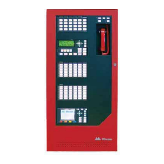
Mircom FX-MNS-6000 Installation And Operation Manual (149 pages)
Network Fire Alarm and Emergency Communication System
Brand:
Mircom
| Category:
Conference System
| Size: 6.43 MB
Table of Contents
Table of Contents
3
Introduction
10
The FX-MNS-6000 Network Fire and Emergency Communication System
10
Document Conventions
13
FX-MNS-6000 Fire and Audio Expansion System Layout
13
Figure 1 Typical FX-MNS-6000 Layout
14
FX-MNS-6000 Fire with Audio Expansion System Layout
15
Figure 2 Typical FX-MNS-6000 Layout with Audio Expansion
15
System Components
16
Table 1: FX-6000MNS System Components
16
Installation
22
BBX-FXMNS-6000 Enclosure Installation
22
Figure 3 BBX-FXMNS-6000 Enclosure
22
Figure 4 BBX-FXMNS-6000 Enclosure Complete View
23
Figure 5 FX-6000MNS-CH Mounted Within the BBX-FXMNS-6000 Enclosure
24
Figure 6 BBX-FXMNS-6000 Backbox Dimensions and Contents
25
Figure 7 BBX-FXMNS-6000 Inner Door
26
QBB-6001 Expansion Audio Cabinet Installation
27
Figure 8 QBB-6001 Dimensions, Mounting Holes and Knockouts for Installation
27
QBB-6001 Enclosure
28
Figure 9 QBB-6001 Expansion Audio Cabinet Module Placement
28
Display Modules
29
Module Settings
30
Main Fire Alarm Module (MD-871A "N" Version Main Chassis)
30
DSPL-420DS Main Display Module
31
Figure 10 Main Fire Alarm Module
31
Figure 11 DSPL-420 Main Display Module (Part of Main Chassis C/W Main Fire Alarm Module)
31
DSPL-2440 Graphical Main Display Module
32
Figure 12 DSPL-2440 Graphical Main Display Module
32
FNC-2000 Fire Network Controller Module
33
Figure 13 FNC-2000 Fire Network Controller Module
33
Table 2: FNC-2000 Module List of Connectors and Jumpers and Functions
33
FOM-2000-UM Fiber Optic Network Module
34
Figure 14 FOM-2000-UM Fiber Optic Network Module
34
Table 3: FOM-2000-UM Fiber Optic Network Module Cable Connection
34
RAX-1048TZDS Zone Display Module
35
Figure 15 Zone Display Module (RAX-1048TZDS)
35
Table 4: RAX-1048TZDS Zone Display Module Cable Function
35
IPS-4848DS Programmable Input Switches Module
36
Figure 16 IPS-4848DS Programmable Input Switches Module
36
Table 5: IPS-4848DS Programmable Input Switches Module Cable Function
36
IPS-2424DS Programmable Input Switches Module
37
Figure 17 IPS-2424DS Programmable Input Switches Module
37
Table 6: IPS-2424DS Programmable Input Switches Module Cable Function
37
FDX-008W(KI) Fan Damper Control Display Module
38
Figure 18 Fan Damper Control Display Module (FDX-008W(KI))
38
Figure 19 FDX-008W Block Diagram of Fan and Monitor Set-Up
39
Figure 20 FDX-008WKI Fan Damper Control Display Module
40
4.10 DM-1008A Hardwire Detection Adder Module
41
Figure 21 Hardwire Detection Adder Module (DM-1008A)
41
4.11 SGM-1004A Hardwire Signal Adder Module
42
Figure 22 Hardwire Signal Adder Module (SGM-1004A)
42
4.12 RM-1008A Hardwire Relay Adder Module
43
Figure 23 Hardwire Relay Adder Module (RM-1008A)
43
Polarity Reversal and City Tie Module (Model PR-300)
44
Figure 24 Polarity Reversal and City Tie Module
44
Table 7: PR-300 Jumper Settings
44
4.14 Udact-300A Main Board
45
Figure 25 UDACT-300A Board Layout
45
Table 8: UDACT-300A Cable Connectors and Miscellaneous
45
Table 9: UDACT-300A List of Leds and Their Functions
46
Table 10: UDACT-300A List of Jumpers for Operation and Configuration
46
ALCN-792MISO Isolated Quad Loop Adder Module with ALCN-792D Daughter Board
47
Figure 26 ALCN-792MISO Quad Loop Adder Module
48
Figure 27 ALCN-792D Daughter Board
49
Field Wiring for Fire Alarm
50
Main Fire Alarm Board Wiring
50
Figure 28 Main Fire Alarm Controller Board Field Terminal Connections
50
Figure 29 Main Fire Alarm Control Board Field Terminal Connections (Continued)
51
Addressable Loop Wiring
52
Figure 30 Loop Terminal Connections - Class B
52
Figure 31 Loop Terminal Connections - Class X (Formerly Style 7)
53
Figure 32 Loop Terminal Connections - Class a
54
Figure 33 Quad Loop Terminal Connections - Class B
55
Figure 34 Quad Loop Adder Module Terminal Connections - Class X (Formerly Style 7)
56
Figure 35 Quad Loop Adder Module Terminal Connections - Class a
57
Network Wiring
58
Figure 36 Class X Wiring for the FNC-2000 Module
58
Figure 37 FOM-2000-UM Fiber Optic Network Adder Module Wiring
59
Analog Initiating Wiring
60
Figure 38 Hardwire Detection Module (DM-1008A) Terminal Connections
60
Analog NAC Wiring
61
Figure 39 Hardwire Signal Module Terminal Connections
61
Analog Relay Wiring
62
Figure 40 Hardwire Relay Module Terminal Connections
62
Polarity Reversal and City Tie Module (PR-300) Wiring
63
Figure 41 Polarity Reversal and City Tie Module Terminal Connection
63
UDACT-300A Main Board Terminal Connections
64
Figure 42 Telephone Line Wiring Diagram
64
Power Supply Wiring
65
Figure 43 Power Supply Connections
65
Figure 44 Power Supply Connections Within BBX-FXMNS-6000 Enclosure
66
5.10 Wiring Tables and Information
67
Table 11: Wiring Table for Initiating Circuits
67
Table 12: Wiring Table for Nacs
67
Table 13: Analog Loop Wiring
68
Field Wiring of Audio
69
QBB-6001 Enclosure (Expansion Cabinet) Assembly
69
Figure 45 QBB-6001 Expansion Audio Cabinet Module Placement
69
Installing and Removing Amplifiers
70
QCC-6000 Communications Card
71
Figure 46 QCC-6000 Communications Card
72
Figure 47 QCC-6000 Rotary Switch
72
Figure 48 Installing the QCC Communications Card
73
Figure 49 QCC-6000 Communications Class B Wiring
74
Figure 50 QCC-6000 Communications Class a Wiring
74
Audio Network Card and Telephone Network Card
75
Figure 51 Mounting the Audio and Telephone Card over the Main Fire Alarm Board in
75
ANC-6000 Audio Network Controller Board
76
Figure 52 ANC-6000 Audio Network Controller Board
76
ANC-6000 Wiring
77
Figure 53 ANC-6000 Wiring Diagram
77
QMP-6101NV Vertical Paging Control Module
78
Figure 54 QMP-6101NV Vertical Paging Control Module
78
Paging Modules
79
Figure 55 QMP-6101NV Network Master Paging Control Module Connections and
79
QAZT-5348DS Zoned Paging Selector Panel
80
QMP-6101NV Paging Operation
81
QMP-6101NV Leds
81
QMP-6101NV Pushbutton Controls
82
QAZT-5348DS Paging Selector Panel Leds
82
QAZT-5348DS Pushbuttons
82
TNC-5000 Telephone Network Controller Module
83
Module Mounting Locations
83
Typical Addressable Telephone Set-Up
83
Figure 56 Typical Addressable Telephone Set-Up
83
Connectors and Terminal Locations
84
Figure 57 TNC-5000 Telephone Network Controller Board Layout
84
Table 14: TNC-5000 Connectors and Terminals
84
TNC-5000 Telephone Wiring
85
Figure 58 Telephone Bus Wiring Diagram
85
Figure 59 TNC-5000 Telephone Zone Wiring
86
QMT-5302NV Vertical Master Telephone
87
Figure 60 QMT-5302NV Master Firefighters' Telephone
87
QMT-5302NV Connections
88
Figure 61 QMT-5302NV Cable Connection and Terminal Wiring
88
QAZT-5348DS Network Firefighters' Telephone Selector Panel
89
Figure 62 QAZT-5348DS Network Firefighters' Telephone Selector Panel
89
Telephone Operation
90
QMT-5302NV Master Telephone Leds
90
QMT-5302NV Master Telephone Pushbutton Controls
90
Figure 63 QAZT-5348DS Telephone Selector Panel Cable Connections
90
QAZT-5348DS Network Telephone Selector Panel Leds
91
QAZT-5348DS Network Telephone Selector Panel Pushbuttons
91
Audio Amplifier Wiring
91
Amplifier Mounting Installation
91
Figure 64 Installing the Amplifiers into the QMB-6000 Card Cage
92
Figure 65 QMB-6000 Terminals for Amplifier Wiring
93
Amplifier Wiring
94
Figure 66 Wiring for 100 Watt Amplifier Circuit
94
Table 15 End of Line Resistor Value for Amplifier Circuits
95
Figure 67 Wiring for 75W and 25W Amplifier Circuits
96
Figure 68 Wiring for 50W Amplifier Circuits
97
Figure 69 Wiring for 25W Amplifier Circuits
98
Table 16 Wiring Chart for 70V Speakers
99
Indication
100
Amplifier Displays
100
Figure 70 Audio Cabinet Displays and Controls
100
Table 17 Wiring Chart for 25V Speakers
100
Audio Configuration
101
System Checkout
102
Before Turning the Power on
102
Power-Up Procedure
102
Troubleshooting
102
Indicators, Controls, and Operation
103
Figure 71 Indicators and Control Location
103
Common Indicators
104
Common Controls
105
Single Stage Operation
108
Two Stage Operation
108
Pre-Signal Operation
110
Circuit Types
110
Figure 72 Evacuation Codes
112
Configuration
113
Configuration Backup, Query and Fast-Forward
113
OPEN Graphic Navigator Software Package
113
Ethernet Port
113
Boolean Logic Engine
114
Multiple Configuration File Support
114
Appendix A: Specifications
115
Compliance
116
FX-MNS-6000 Audio Specifications
117
Table 18FX-MNS-6000 Audio Specifications
117
Appendix B: Power Supply and Battery Calculations
118
16.1 Raxn-Lcd/Raxn-Lcdg
119
Appendix C: DIP Switch Settings
120
FX-6000MNS-CH Network Main Board Address Setting (DIP SWITCH SW2)
120
ANC-6000 Audio Network Controller Board Address Setting (DIP SWITCH SW1)
121
ACN-792MISO Loop Adder Module (CPU) Address Setting (DIP SWITCH SW1)
121
Advertisement
Mircom FX-MNS-6000 Configurator Manual (178 pages)
Network Intelligent Fire Alarm and Audio System
Brand:
Mircom
| Category:
Fire Alarms
| Size: 2.77 MB
Table of Contents
Table of Contents
2
Configuration
7
Overview
8
GUI - Major Components
8
Edit Menu
9
File Menu
10
Insert Menu
11
Job Menu
12
Panel Menu
14
Tools Menu
15
Add Amplifier
16
Add Circuit Adder
16
Add Correlations
18
Add Device
18
Add Group
20
Add Display Adder
21
Add Loop Controller
22
Add Message
23
Add Network Node
23
Add an Output Group
24
Add UDACT
27
Add Zone
28
Address Scheme
29
Advanced Panel Information Dialog
30
Node Control (Request/Grant/Deny)
31
Node Grouping
39
Audio Message Composer
41
Audio Setup
45
Backup Database
46
Manage Messages
48
Select Job to Compare
49
Compare Jobs Advanced Options
50
Create Job
51
Display Structure
52
Edit Job
54
Export Job
55
Firmware Archive Contents
57
Holidays
58
Import Job
59
Logic Editor Dialog
60
Network Node Merge
69
New Job Version Information
69
Open Job
70
Panel Information Dialog
71
Paste Special
72
Paste Special
73
Print Dialog
75
Print Setup
77
Restore Database
77
Security Key Logon
78
Upgrade Firmware
80
User Preferences
82
Update Panel Time
83
Version History
83
XML Export / Job Details Options Dialog
84
Audio Controller Details
85
System/Node/Cpu Status
87
Correlations
90
Interval List View
92
Timer List View
94
Dialer
95
Display Adder
100
Equation Summary List View
103
Input / Output Circuit Summary
104
Input Zones
106
Audio Splitter Zones
108
LED Annunciator Summary
108
Loop Controller
109
Loop Detail
110
Main Display / LCD Annunciator
114
Job Details
118
Job Tree
126
Network Node Details
128
Walk Test Areas
130
Drift Compensation
131
Differences Mode / Differences Report
132
Fire Phone Configuration
136
Send Job
142
Get Job
142
Suite Silence Configuration
144
Delete Item
146
Modify Item
146
Copy
146
Paste
147
Paste Special
147
User Preferences
147
Print
147
Print Preview
147
Add Loop Controller
147
Add Annunciator
148
Add Display Adder
148
Add Item
148
Add Device
148
Add Correlations
149
New Job
149
Open Job
150
Merge Job
150
New Version
151
Delete Job Version
152
Version History
152
Convert Job
152
Validate Job
152
Panel Info
153
Security Key Information
153
Upgrade Firmware
153
Extract All
153
Build Job
153
Connect
153
Manage Jobs
153
Build Job
154
Link Statistics
154
Display Structure
154
Custom Messages
154
Security Key Information
157
System Status Details
157
Node Status Details
164
CPU Status Details
167
Linked Display Items
171
Convert Job
172
Copy and Paste
173
Add Annunciator
176
Select Build Type
176
Advertisement
Related Products
Mircom FA-102T
Mircom FX-350 Series
Mircom FleX-Net FX-4000
Mircom FleX-Net FX-4000N
Mircom FleX-Net FX-2003-12NDS
Mircom FleX-Net FX-2003-12NXTDS
Mircom FleX-Net FX-2017-12NDS
Mircom FleX-Net FX-2009-12NDS
Mircom FleXNet FNC-2000
Mircom FX-3500RCU
Mircom Categories
Control Panel
Intercom System
Fire Alarms
Controller
Smoke Alarm
More Mircom Manuals
Login
Sign In
OR
Sign in with Facebook
Sign in with Google
Upload manual
Upload from disk
Upload from URL