Sign In
Upload
Manuals
Brands
Mindray Manuals
Medical Equipment
WATO EX-65Pro
Mindray WATO EX-65Pro Manuals
Manuals and User Guides for Mindray WATO EX-65Pro. We have
1
Mindray WATO EX-65Pro manual available for free PDF download: Service Manual
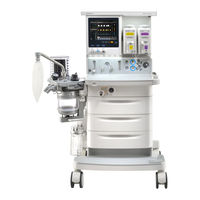
Mindray WATO EX-65Pro Service Manual (475 pages)
Anesthesia Machine
Brand:
Mindray
| Category:
Medical Equipment
| Size: 20.27 MB
Table of Contents
Intended Audience
4
Manual Purpose
4
Password
4
Preface
4
Table of Contents
5
Safety Information
13
Warnings
13
Cautions
14
Notes
14
2 Theory of Operation
15
Electrical Part
15
Outside Ports
16
Electrical Theory
17
Theory Diagram
17
Hardware Components List
18
Mother Board
20
Power System
29
Power Board
29
Signal Flow When Powering on
30
Battery Adapter Board
32
Auxiliary Electrical Outlet
33
Display System
35
Others (Heating Module, Fan, Lithium Battery)
35
Key Control Adapter Board
35
Screnn and Touchscreen
38
Alarm Light Board
38
Encoder Board
39
Control System
40
Main Control Board
40
Monitoring Module
45
VCM
46
Vpm
48
EFCS Flowmeter System
51
Efcs VCM
51
Flowmeter Control Board
53
Gas Parameter System
54
Infrared Communication Board
54
Others
55
Top Light Board
55
Auxiliary Light Board
56
Flowmeter Backlight Board
57
Indicator Board
58
Pneumatic Part
59
Pneumatic Circuit Diagram
59
Pneumatic Components and Symbles
60
Key to Symbols
61
Gas Supplies
62
Pipeline Supply System
62
Backup Supply System
64
Anesthetic Gas Delivery System
65
System Switch Assembly
65
Electronic Flow Control System-EFCS
66
Flow Control System-BFCS
67
Vaporizer Manifold
68
ACGO Assembly
69
O2 Flush Button Assembly
69
Auxiliary Supply Assembly
70
Drive Gas Switch Assembly
70
Breathing System
71
Overview
71
Mechanical Ventilation
73
Manual Ventilation
73
Mechanical Inspiration Mode
73
Mechanical Expiration Mode
73
Gas Bench
74
O2 Sensor
74
Anesthesia Calculation Module
75
Pneumatically-Controlled Module of Anesthetic Ventilator
75
Anesthetic Gas Scavenging System
76
Breathing System Heater
77
Ventilator Pneumatic - O2 Drive Gas
77
Drive Gas Assembly
78
Negative Pressure Suction System
78
Drive Pressure - High Pressure Regulator (200 Kpa, 29 Psi)
78
3 Installation Guide
79
Preparation
79
Assembly
79
Unpacking and Setup
80
Breathing System, Breathing System Accessories and Checkout Procedures
95
AGSS Connections
95
Vaporizer
96
Cylinder Wrench and User Guide
96
Assemble the Vaporizer
97
Fill the Vaporizer
98
Drain the Vaporizer
98
Cylinder Installation
99
Patient Circuit and CO2 Absorbent
99
Anesthesia Module Installation and Waste Gas Scavenging
100
Negative Pressure Suction
100
Monitoring Products Mounting and Electrical Connection (Optional)
100
4 Testing
101
System Inspection
101
System Self- Test
102
Automatic Circuit Leak and Compliance Test
103
Manual Circuit Leak Test
104
Gas Supply Tests
105
Troubleshooting-Leak Test
105
O2 Pipeline Supply Test
105
N2O Pipeline Supply Test
106
Air Pipeline Supply Test
106
O2 Cylinder Supply Test
106
EFCS Accuracy Test
107
N2O Cylinder Supply Test
107
Air Cylinder Supply Test
107
BFCS Function Tests
108
Checking Switchover between the EFCS and BFCS
108
Flow Control System Tests
109
Checking Needle Valve Correspondence
109
Checking the Needle Valve Sensitive Switch
109
Without O2 Sensor
109
With O2 Sensor
111
Vaporizer Back Pressure Test
112
Vaporizer Interlock Test
112
Vaporizer Accuracy Test
113
Vaporizer Leak Test
114
Other Functional Tests
115
Drive Gas Switching Function Test
115
Auxiliary O2 Supply Flowmeter Accuracy Test
115
O2 Flush Test
116
In Mechanical Ventilation Mode
116
In Manual Ventilation Mode
116
ACGO Function Tests
117
AGSS Inspection
117
ACGO Switch Alarm Test
117
ACGO Pressure Detection Function Test
117
Check the Transfer Tube and Active Scavenging Tube
118
Negative Pressure Suction Inspection
119
Check the Tube Connections of Liquid Collection Bottle
119
Check the Negative Pressure
119
Breathing Circuit Tests
120
Check Valve Test
120
Bellows Test
121
Breathing System Leak Test in Manual Ventilation Mode
121
Software Auto Test
121
Manual Test
122
Commonly-Encountered Problems and Recommended Actions
122
Definitions of Error Information During Breathing System Leak Test
123
Breathing System Leak Test in Mechanical Ventilation Mode
123
Test Procedures
123
APL Valve Test
127
O2 Sensor Related Tests
127
O2 Sensor Disconnection Alarm Test
127
Bypass Function Test
128
O2 Concentration Test
128
Prepare for Alarm Tests
129
Test the Apnea Alarm
130
Test the Sustained Airway Pressure Alarm
130
Test the O 2 Concentration Monitoring and Alarms
130
Test the Low Minute Volume (MV) Alarm
130
Test the High Paw Alarm
131
Test the Low Paw Alarm
131
Breathing System Not Mounted Alarm Test
131
CO2 Absorbent Canister Alarm Test
131
System Ventilation Performance Tests
132
O2 Supply Failure Alarm Test
132
Drive Gas Pressure Low Alarm Test
132
Power Failure Test
132
Standby Mode Ventilation Test
132
Manual Mode Ventilation Test
133
VCV Adult Ventilation Mode Test
133
VCV Child Ventilation Mode Test
134
Air Way Disconnection Alarm Test
134
PCV Adult Ventilation Mode Test
135
State Test of Sensors
136
Checking the Sensor Zero Point
136
Constant Flow Test (Checking the Flow Sensor Accuracy)
137
Constant Pressure Test (Checking the Pressure Sensor Accuracy)
141
Electrical Safety Inspection
146
Auxiliary Electrical Outlet Test
146
Top Light, Auxiliary Gas Supply and Total Flowmeter Backlight Test
146
Total Flow Sensor Self Test
146
Electrical Safety Inspection Form
147
Electrical Safety Inspection Test
147
5 Factory Maintenance Menu
149
Calibration
149
Data Monitors
150
Valves Diagnostic Test Tools
161
Valves Test
161
Insp. Valve Test
163
PEEP Valve Test
165
Safety Valve Test
165
Review Logs
165
System Info
166
Demo Mode
167
Restore All Default
167
Factory Setup
168
Function Activation
169
Drive Gas Auto Switch
169
Flowmeter Standard
169
Air Pressure Switch Sensor
169
Flowmeter Pipeline
169
Acgo
170
Module Rack
170
AG Module
170
BIS Module
170
CO2 Module
170
6 Device Maintenance
171
Maintenance Overview
171
Maintenance Period
171
System Check
172
Maintenance Package Parts
172
One-Year Replaceable Parts
172
Parts Replacement
176
Non-Circuit Part
176
Non-Pre-Pak Circuit Part
177
Pre-Pak Circuit
183
Checkout and Test of the Anesthesia Machine
185
Other Materials Need to be Checked and Replaced
186
Tests after Maintenance
186
Maintenance and Replacing of Battery
186
Check the Mechanical Ventilation Mode
188
Сheck Volume Control Ventilation (VCV)
188
Check Pressure Control Ventilation (PCV)
189
Breathing System Leak Test in Mechanical Ventilation Mode
190
Breathing System Leak Test in Manual Ventilation Mode
190
Check the Sensor Zero Point
191
Check the Flow Sensor Accuracy
192
Check the Pressure Sensor Accuracy
193
Check the Electronic Flowmeter Accuracy
194
Check the O2/Air Electronic Flowmeter Accuracy
194
Check the N2O Electronic Flowmeter Accuracy
195
7 System Calibration
197
Precautions
197
Overview
197
Warnings
197
Cautions
198
Notes
198
System Calibration
199
Flow Calibration (User)
200
Flow Calibration Principles
201
Calibration (User) Procedure
202
Schematic Diagram of Flow Calibration
205
Flow Calibration (Service)
205
Calibration Procedure
206
Common Failures and Recommended Actions
218
Pressure Calibration (Service)
223
Pressure Calibration Principles
224
Schematic Diagram of Pressure Calibration
224
Zeroing Mechanisms
235
Zeroing Procedure
235
Pressure and Flow Zeroing (Service)
235
EFCS Flowmeter Zeroing (User)
237
O2 Sensor Calibration
241
21% O2 Calibration
241
100% O2 Calibration
243
Calibration Mechanisms
247
Total Flow Sensor Calibration (Factory)
247
Calibration (Factory) Procedure
248
Calibration Procedures
250
CO2 Calibration (Factory)
250
AG Calibration (Factory)
252
O2 Module Calibration (Factory)
253
Troubleshooting Guide
255
Fault Determination
255
Avoiding Short Circuit of Component Leads
255
Using Appropriate Tools
255
Technical Alarms
256
Cleanup of the Maintenance Area
256
Startup Alarm Messages
256
CPU Board Runtime Alarms
261
Power Board Runtime Alarms
262
Electronic Flowmeter Board Runtime Alarms
264
VCM Board Runtime Alarms
266
Keyboard Runtime Alarms
270
External AG Module Runtime Alarms
271
BIS Module Runtime Alarms
273
CO2 Module Runtime Alarms
277
Mainstream CO2 Module
278
Microstream CO2 Module
279
Leak and Compliance Tests
280
Airway System Failure
283
Troubleshooting—Leak Test
283
Onsite Maintenance Tools
284
Negative Pressure Ball
287
Test Fixture of the Circuit Transit Adapter
287
Test Fixture of the Pressure Sampling Line of the Flow Sensor
287
Test Fixture of the Vaporizer Support
288
Anesthesia Machine Calibration Device
288
1 Mpa Test Pressure Gauge
288
Use of Test Fixture of Pressure Sampling Tube of Flow Sensor
291
Precautions for Use of Test Fixture of Vaporizer Support
292
Precautions for Use of Negative Pressure Ball
293
Effectiveness Test for Pipeline Pressure Gauge/Correction of Regulator
294
Testing Pipeline Pressure Gauge and Calibrating the Regulator
295
O2 Inlet Assembly
296
N2O Inlet Assembly
297
Testing the Pressure Switch
298
Air Inlet Assembly
298
Adjusting the Pressure Switch
300
AG Transmission System
301
Adjusting the Regulator of the Pipeline Gas Inlet Assembly
301
Leakage Test on the O2 Flush Button Assembly
303
Leak Test for the Auxiliary Oxygen Flowmeter Assembly
303
Leak Test for the Backup Oxygen Flowmeter Assembly
304
Leak Test for the EFCS Flowmeter Assembly
305
Leakage Test on the System Switch Assembly
306
Leakage Test on Vaporizer Support Assembly
307
Leakage Test on the Sampling Line of the Flow Sensor
312
Leakage Test on the Low-Pressure Airway System
314
Leakage Test on Manual Ventilation
315
Leakage Test on Internal Pipelines
315
Lucer Adapter Connector
322
Bypass Disabled
322
Bypass Enabled
322
Tidal Volume
325
Sensor and Valve Faults
327
Mapping between Menu Items on the Valve Diagnosis
328
Tool Interface and Airways
328
Tool Interface and Hardware Components
329
Preparations before Using the Valve Diagnosis Tool
330
Diagnosing Zero Point Exceptions of Sensors
330
Diagnosing Flow Data Exceptions of Sensors
330
Diagnosing Pressure Data Exceptions of Sensors
332
Diagnosing Inspiratory Valve Exceptions
333
Diagnosing PEEP Safety Valve Exceptions
334
Diagnosing PEEP Proportional Valve Exceptions
334
Gas Source and Drive Gas Faults
335
Testing the Pipeline Pressure Gauge and Calibrating the Regulator
336
O2 Supply Inlet
336
N2O Supply Inlet
338
Air Supply Inlet
340
Hardware and Electrical Faults
344
Adjusting the Regulator of the Pipeline Gas Supply Inlet
344
Software Upgrade and Software Configuration
347
Activation
347
Common Software Upgrade Problems and Solutions
351
Software Function Activation
352
Applying for Activation Codes
352
Software Function Activation Procedure
353
Common Software Function Activation Problems and Solutions
355
Repair and Disassembly
357
Prepare for Disassembly
358
Tools
358
Preparations
358
Disassemble Assemblies
359
Release Pressure
359
Remove Top Cover Assembly and Top Plate Assembly
359
Remove Speaker
360
Remove Top Light Board and Switch
361
Remove Service Door and Rear Cover Plate
361
Remove Cart Rear Cover Plate Assembly
362
Remove Module Rack Box Assembly
363
Remove Module Rack Fan
363
Remove Display Assembly
364
Remove Key Control Board
365
Remove Work Surface Light Board
366
Remove the Alarm Lamp Board
367
Remove Encoder Board and Encoder
367
Remove Display and Touch Screen
368
Remove Hardware Box Assembly
369
Replace Fuse
372
Replace Battery
372
Remove EFCS Flowmeter
373
Remove EFCS Flowmeter Board
374
Remove Flowmeters
375
Remove Proportional Valve, Three-Way Valve and Two-Way Valve
376
Remove Vaporizer Manifold
377
Remove Gas Source Inlet Port Assembly
377
Remove Backup Gas Source Inlet Port Assembly
379
Remove Backup Cylinder Bracket
380
Remove Cover Plate of Work Surface
381
Remove Exhalation Valve Assembly
383
Remove ACGO Assembly
383
Remove Gas Reservoir Assembly
384
Remove O2 Flush Assembly
384
Remove High-Pressure Gauge Assembly
385
Remove Gas Supply Pressure Gauge Assembly
386
Remove Negative Pressure Control Panel Assembly
387
Remove Backup O2 Flowmeter Assembly
387
Remove System Switch Assembly
388
Remove Indicator Light Board
388
Remove Drive Gas Switching Valve
389
Remove Power Cable
389
Remove Drawer
390
Remove Air Compressor
391
Remove Cart Slide
392
Remove Lock of Drawers
392
Disassemble Breathing System
394
Remove O2 Sensor
394
Remove Breathing Tubes
395
Remove Flow Sensor
397
Remove Manual Bag
398
Remove Bellows Assembly
398
Remove Pop-Off Valve Assembly
399
Remove Expiratory Check Valve Assembly
400
Remove Inspiratory Check Valve Assembly
401
Remove CO2 Absorbent Canister
402
Remove Water Collection Cup
403
Remove Airway Pressure Gauge
404
Remove Bag Arm
404
Remove Breathing System
405
Remove CO2 Absorbent Canister Connection Block Assembly
406
Remove Back Upper Cover and Back Lower Cover Assemblies
408
Remove Front Upper Cover
409
Remove Median Plate Assembly
410
Remove Lower Cover Assembly
411
Remove Bag/Vent Switch Assembly
411
Remove APL Valve Assembly
413
Disassemble the Breathing System
414
Remove the Absorbent Canister
417
Remove CO2 Bypass Assembly
418
Remove Drain Valve
418
Remove Bypass Valve and the Trigger Board
419
Remove Patient Circle Assembly
421
Remove Expiratory/Inspiratory Check Valve Assemblies
423
Remove the Back Upper Cover and Back Lower Cover Assemblies
425
Remove Front Upper/Lower Cover, Median Plate and Assemblies
426
Remove Automatic/Manual Ventilation Switch Assembly
428
Electrical Connections
431
Electrical Circuit Diagram
431
Board List
432
Connection Line List
433
Pneumatic Connection A: System Pneumatic Connection Diagram
435
Pneumatic Connection B: System Pneumatic Connection Diagram
436
Pneumatic Connection C: System Pneumatic Connection Diagram
437
Replacement Parts
439
Introduction
439
Ordering Replaceable Parts
439
Diagrams and Tables
440
Upper Half
444
Hardware Box
447
Work Surface
451
WATO EX-55 Pro/65 Pro Auxiliary O2 Supply Flowmeter Assembly
454
WATO EX-55 Pro/65 Pro Cart Assembly
455
WATO EX-55 Pro/65 Pro Pre-Pak Circuit Bracket Assembly
457
Breathing Circuit Adapter Block Assembly
459
Main Body of the Breathing Circuit
460
CO2 Absorber Canister Assembly
461
Absorbent Canister Assembly Compatible with Pre-Pak
461
Absorbent Canister Assembly Not Compatible with Pre-Pak
463
Expiratory Check Valve and Inspiratory Check Valve
465
O2 Cell Assembly
465
WATO EX-55 Pro/65 Pro Display Assembly
466
WATO EX-55 Pro/65 Pro Backup Flowmeter Assembly
467
Base Assembly
468
Tubes
471
O-Ring
472
Advertisement
Advertisement
Related Products
Mindray WATO EX-65
Mindray WATO EX-55
Mindray WATO EX-55Pro
Mindray SynoVent E5
Mindray ePM 10M
Mindray ePM 10MA
Mindray ePM 10MC
Mindray ePM 12MA
Mindray ePM 12MC
Mindray Eagus I9
Mindray Categories
Medical Equipment
Diagnostic Equipment
Measuring Instruments
Monitor
Water Pump
More Mindray Manuals
Login
Sign In
OR
Sign in with Facebook
Sign in with Google
Upload manual
Upload from disk
Upload from URL