Sign In
Upload
Manuals
Brands
Mindray Manuals
Diagnostic Equipment
DC-80A
Mindray DC-80A Ultrasound System Manuals
Manuals and User Guides for Mindray DC-80A Ultrasound System. We have
2
Mindray DC-80A Ultrasound System manuals available for free PDF download: Operator's Manual, Service Manual
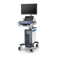
Mindray DC-80A Operator's Manual (392 pages)
Diagnostic Ultrasound System
Brand:
Mindray
| Category:
Diagnostic Equipment
| Size: 9.82 MB
Table of Contents
Table of Contents
3
Contents
7
Intellectual Property Statement
7
Responsibility on the Manufacturer Party
7
Warranty
8
Exemptions
8
Customer Service Department
9
Important Information
10
About this Manual
10
Notation Conventions
10
Operator's Manuals
11
Hardcopy Manuals
11
Software Interfaces in this Manual
11
Conventions
12
Product Difference
12
1 Safety Precautions
13
Safety Classifications
13
Meanings of Signal Words
14
Meaning of Safety Symbols
14
Safety Precautions
15
Latex Alert
22
Warning Labels
23
2 System Overview
25
Intended Use
25
Contraindication
25
Product and Model Code
25
Product Specifications
26
System Configuration
27
Environmental Conditions
27
Dimensions and Weight
27
Probes and Needle-Guided Brackets Available
27
Options
29
Peripherals Supported
32
Introduction of each Unit
33
Product View
33
I/O Panel
35
Power Supply Panel
36
Physio Panel
37
Control Panel
38
Keyboard
40
Common Functional Keys
40
Functions of the F1 to F12 Keys
41
Fn Key
42
Symbols
43
3 System Preparation
45
Move/Position the System
45
Connecting the Power Cord & Protective Grounding
46
Powered by Battery
46
Equipotential Terminal
47
Power the System on
48
Power the System off
49
Standby
50
Monitor Position Adjustment
51
Height and Displacement Adjustment
51
Rotate the Monitor
51
Lock the Monitor
52
Control Panel Position Adjustment
53
Connecting a Probe
53
Connecting Peripheral Devices
54
Disconnecting a Probe
54
Connecting USB Devices
54
Connecting a Foot Switch
54
Function Setting
55
Installing a Graph/Text Printer
56
Installing a Video Printer
56
Position the Printer
57
Installing/ Uninstalling Probe/Gel Holder
57
Basic Screen & Operation
60
Screen Display
60
Patient/Exam Information
60
Basic Operations of the Dialog Box
62
Menu Operation
63
Touch Screen Operation
64
Mapping Mode
64
Menu Operations
64
Soft Menu Operations
65
Two-Finger Gesture
65
Operations on Tool Bar
65
Soft Keyboard
66
Non-Mapping Mode of Touch Screen
66
4 Exam Preparation
69
Patient Information
69
New Patient Information
70
Exam Type
71
Exam-Specific Information
71
Retrieve Patient Information
73
Istation
73
Operating Information
73
Functional Keys
73
Worklist
76
Select Exam Mode and Probe
78
Select the Imaging Mode
78
Dual-Probe Switch
78
Activate & Continue an Exam
79
Pause & End an Exam
79
5 Image Optimization
81
Imaging Mode
81
Switching between Imaging Modes
81
Image Adjustment
81
Recently Used Exam Modes
82
Knob-Adjusting Area
82
Touch the Item on the Touch Screen to Operate
82
B Mode Image Optimization
83
Quickly Saving Image Settings
83
Basic Procedures for B Mode Imaging
84
B Mode Parameters
84
Image Quality
84
Gain
84
Depth
85
Tgc
85
Acoustic Power
85
Focus
85
Imaging Adjustment
86
Line Density
86
Dynamic Range
86
Iclear
87
Persistence
87
Rotation/Invert (U/D Flip and L/R Flip)
87
Ibeam (Spatial Compound Imaging)
87
Image Merge
88
Gray Map/Tint Map
88
TSI (Tissue Specific Imaging)
88
Itouch (Auto Image Optimization)
88
H Scale
89
Dual Live/Lgc
89
Echo Boost
89
Dehaze
89
M Mode Image Optimization
90
M Mode Image Parameters
90
Ref. Line
90
Display Format
91
Speed
91
Color Mode Image Optimization
92
Edge Enhance
92
M Soften
92
Time Mark
92
Basic Procedures for Color Mode Imaging
93
Color Mode Image Parameters
93
ROI Adjustment
94
B/C Align
94
Dual Live
94
Steer
94
Packet Size
95
Flow State
95
Smooth
95
Scale
96
Baseline
96
Invert
96
Color Map
96
WF (Wall Filter)
97
Smart Track
97
Priority
97
Velocity Tag
97
Power Mode Image Optimization
98
Basic Procedures for Power Mode Imaging
98
Power Mode Image Parameters
98
HR Flow (High Resolution Flow)
98
Power Gain
99
Basic Procedures for PW/CW Mode Exam
100
PW/CW Mode Image Parameters
100
PW/CW Mode Image Optimization
101
CW Focus Position
101
Auto-Calculation
102
T/F Res
103
Wall Filter
103
Duplex/Triplex
104
Hprf
104
Angle
105
Quick Angle
105
Audio
105
PW Steer
105
Enter Color M Mode
106
Exit Color M Mode
106
Color M Mode Image Parameters
106
Anatomical M Mode
107
Free Xros M Imaging (Anatomical M-Mode)
107
Free Xros M Image Parameters
107
Display/Hide the M-Mark Line
107
Free Xros CM (Curved Anatomical M-Mode)
108
Exit Free Xros M
108
Switching between the M-Mark Lines
108
Adjusting the M-Mark Line
108
TDI Mode
109
Basic Procedures for TDI Imaging
109
Sample Line Modification
109
Delete a Sample Line
109
TDI Image Parameters
110
TDI Image Optimization
110
TDI Quantitative Analysis (QA)
110
TDI QA Screen Description
111
Basic TDI QA Procedures
112
Setting the ROI
112
Standard ROI
112
Ellipse ROI
112
3D/4D
113
ROI Tracking
113
Export/Save Trace Data
113
Delete an ROI
113
ROI and VOI
114
ROI Size and Position
115
Curved VOI Adjustment
115
About the Probes
115
Mpr
115
3D/4D Image Quality Conditions
117
Free View (Free View Imaging)
117
Wire Cage
117
Fetal Condition
117
Basic Procedures for Static 3D Imaging
118
Angle of a B Tangent Plane
118
Image Quality in B Mode (2D Image Quality)
118
Scanning Technique (Only for Smart 3D)
118
For Setting the ROI
119
Static 3D Acquisition Preparation
120
Static 3D Image Viewing
120
Enter/Exit Image Viewing
120
Activate MPR
121
MPR Viewing
121
MPR Only
121
Asymmetric
122
View Direction
122
Adjust VOI
123
Image Rendering Parameters
123
VOI On/Off
123
Accept VOI
123
Reset Curve
125
Render Mode
125
Rotate an Image
126
Axial Rotation
126
Auto Rotation
126
Surface Enhancement
127
Move the Light
127
Image Zooming
127
Sync
127
Comments and Body Marks
128
Image Editing
129
The Image Cutting Parameters
129
4D
130
Image Saving and Reviewing in Static 3D
130
Color Static 3D (Color 3D)
130
Basic Procedures for 4D Imaging
130
Smart 3D
131
4D Image Saving
131
3D/4D Fast Switching
131
Smart 3D Acquisition Preparation
132
Smart 3D Image Viewing
133
STIC (Spatio-Temporal Image Correlation)
134
Image Saving and Reviewing in Smart 3D
134
Basic Procedures for STIC
135
Operation Controls
135
3D Layout
136
Ipage+
136
Scv+
140
Color 3D
142
Smart Volume
143
Ilive
144
Results Display
144
Edit the VOI (Volume of Interest)
144
Lighting Mode
146
Light Source Adjustment
146
Smart FLC (Smart Follicles Calculation)
147
Smart Planes CNS
148
Auto Comment
150
Reference Line Rotating
151
MSP Editing
151
Automatic Measurement
152
Smart Face
153
Contrast Imaging
154
Contrast Image Parameters
155
Parameter Area Display
155
Timer
155
Micro-Bubble Destruction
156
MIX Map
156
Itouch
156
Left Ventricular Opacification
157
Micro Flow Enhancement
157
Contrast Imaging QA
157
Image Saving
157
Contrast QA Screen
158
QA Analysis Image Range
158
Setting ROI
159
Motion Tracking
159
X Scale
159
Iscape View (Real-Time Panoramic Imaging)
160
Set Fit Range
160
Curve Fitting
160
Basic Procedures for Iscape Imaging
161
Image Acquisition
161
Iscape Viewing
162
Adjusting Image Parameters
162
Cine Review
163
Measurement, Comments and Body Marks
163
Evaluate Image Quality
163
Rotating the Image
163
Strain Elastography
164
Basic Procedure for Elastography
164
Enter/Exit
165
Strain E Curve
165
STE Imaging (Sound Touch Elastography)
166
Mass Measurement
166
Map Position
166
Strain Scale
166
Basic Procedures for STE Imaging
167
STE Mode Image Optimization
167
Elas Metric
167
Opacity
168
Map
168
Hqelasto
168
RLB Map
169
RLB View
169
M-STB Index/Sensibility
169
Inatural
170
FS Mode
170
Ilayering
170
Measuring
171
Lesion
171
E Avg
171
E Bar
171
Stress Echo
172
Basic Procedures for the STQ Imaging
172
STQ Mode Image Optimization
172
Stress Echo Acquisition Procedure
173
Selecting Preferred Stress Echo Loops (Select Mode)
175
Description of Select Mode Controls
176
Review/Wms Mode
177
Enter Review Mode
177
Wall Motion Scoring
178
Maintenance
179
Protocol Edit
180
QT-Time Table Operation
180
Saving Stress Echo Data
181
Creating a Stress Echo Protocol
181
Editing or Deleting a Stress Echo Protocol
181
Tissue Tracking Quantitative Analysis (QA)
182
Exiting the Stress Echo Feature
182
Tissue Tracking QA Screen Description
183
Select Image and Cardiac Cycle
184
Myocardial Boundary Tracing
185
Tissue Tracking Operations
185
Bull’s Eye
186
Parameter Adjustment
186
Image Display
186
Smart Pelvic Floor
187
Measurement/Comment
187
Data Export
187
6 Display & Cine Review
189
Splitting Display
189
Image Magnification
189
Spot Zoom
189
Freeze/Unfreeze the Image
190
Izoom (Full Screen View)
190
Imaging Mode Switching When Frozen
190
Entering/Exiting Cine Review
191
Cine Review in 2D Mode (B/B+Color/B+Power/B+Tvi/B+Tei)
192
Cine Review in M/PW/CW/TVD Mode
193
Linked Cine Review
193
Image Compare under Review Mode
194
Frame Compare
194
Icompare
194
Cine Saving
195
Setting Cine Length
195
7 Physiological Signal
197
ECG Operation Basic Procedures
198
ECG Triggering
198
Triggering Mode
199
Real & Trigger
199
Respiratory Wave Operation Basic Procedures
200
The Physio Parameters
200
8 Measurement
201
Basic Operations
201
Measurement Results and Help Information
201
To Enter/Exit Measurement
201
2D General Measurements
202
M General Measurements
202
Doppler General Measurements
203
Application Measurements
204
Measurement Accuracy
205
Comments Basic Procedures
207
9 Comments and Body Marks
207
Touch Screen Display in Comments
208
Quickly Select a Comment in a Group
209
Adding a Comment Text
210
Adding an Arrow
210
Adding Comments
210
Typing Comment Characters
210
Modifying (Editing) Arrows
211
Modifying (Editing) Comments
211
Moving Comments
211
Tracing
211
Body Mark
212
Comment Setting
212
Deleting Comments
212
Touch Screen Display in Body Mark
212
Adding Body Marks
213
Deleting Body Marks
213
Moving Body Marks
213
10 Patient Data Management
215
Patient Information Management
215
Image File Management
215
Image File Formats
215
Image Storage Preset
216
Quickly Saving Images to the System
216
Quickly Saving Full Screen Images to the System
217
Quickly Saving Images to USB Flash Drive
217
Quickly Exporting Cine File to USB Flash Drive
217
Auxiliary Output Function
217
Thumbnails
218
Image Review and Analysis
218
Functions in the Review Screen
219
Ivision
221
Sending Image Files
222
Report Management
223
Istation - Patient Data Management
226
Viewing Patient Information
226
Searching a Patient
226
Patient Data View & Management
227
Delete Exam
227
Backup/Restore
227
Send Exams
227
Select Target
228
New Exam
228
Activate an Exam
228
Continue an Exam
228
Recycle bin
229
Istorage
230
Print Setting
230
Image Printing
230
Back up Files Using the DVD Drive
231
Report Printing
231
Patient Task Management
232
Administration
233
Access Control
233
System Login
233
Local Privilege Management
234
Deleting a User
235
Editing Privilege
235
Modifying Passwords
236
Session Manage Page
236
Configuring Password Policy
237
Setting Automatic Machine Locking Time
238
LDAP Privilege Management
239
Adding a User
240
Modifying the Member Name or Privileges
240
Logon Test
240
V-Access
241
User Field Name
241
11 Dicom/Hl7
243
DICOM Preset
244
IP Preset
244
DICOM Local Preset
244
Set DICOM Strategy
245
Server Setting Procedure
245
Storage Service Preset
246
Print Service Preset
249
DICOM Worklist Preset
251
MPPS Preset
251
Storage Commitment Preset
251
Query/Retrieve Preset
251
Output
252
Hl7Query Preset
252
Verify Connectivity
253
DICOM Services
253
DICOM Storage
253
Send Images on Istation/Review/Main Screens
254
To Send Images Using a Shortcut Key
254
To Send Images to Storage after an Exam Ends
254
DICOM Print
255
To Print Images for Storage after an Exam Ends
255
Mpps
256
Storage Commitment
256
Query/Retrieve
257
DICOM Media Storage
258
Data Restore
258
Structured Report
259
Showcase Recording
259
DICOM Task Management
260
12 Setup
261
System Preset
262
Region
263
General
264
Image Preset
265
Exam Mode Preset
268
Comment Preset
269
Measurement Preset
269
Iworks Preset
271
Stress Echo Preset
271
DICOM/HL7 Preset
271
Print Preset
272
Network Preset
273
Istorage Preset
273
Network Settings
273
Modify a Network Service
273
Medtouch/Medsight Preset
275
Remote Maintenance
275
Option
276
Exporting Setup Data
276
Maintenance
276
Importing Setup Data
277
Probe Check
277
Security
278
Other Settings
278
Anti-Virus
279
System Information
280
13 Probes and Biopsy
281
Probe Functions by Part
283
Operating Procedures
284
Orientation of the Ultrasound Image and the Probe Head
284
Wearing the Probe Sheath
287
Probes Cleaning, Disinfection and Sterilization
288
Selecting a Microbicidal Method
289
Low-Level Disinfection of a Non-Critical Probe
290
High-Level Disinfection of a Semi-Critical Probe
291
Compatible Disinfectants
292
Environment
293
Low-Level Disinfectant
293
Storage and Transportation Condition
294
Biopsy Guide
295
Needle-Guided Brackets
298
Plastic/Needle Detachable Needle-Guided Bracket
300
Basic Procedures for Biopsy Guiding
305
Needle-Guided Bracket Inspection and Installation
306
Biopsy Guideline
314
Biopsy Menu/Guideline Verification
314
Removing the Needle-Guided Bracket
315
Ineedle (Needle Visualization Enhancement)
319
Clean and Sterilize the Needle-Guided Bracket
320
Sterilization with a Sterilant
321
High-Pressure Steam Sterilization
322
Hydrogen Peroxide and Peroxyacetic Acid Based Sterilant
322
Storage and Transportation
322
Middle Line
323
14 DVR Recording
325
Send Image
325
DVR Video Replay
326
15 Acoustic Output
327
Concerns with Bioeffects
327
Prudent Use Statement
327
ALARA Principle (as Low as Reasonably Achievable)
327
MI/TI Explanation
328
Basic Knowledge of MI and TI
328
Mechanical Bioeffect and Thermal Bioeffect
328
TI (Thermal Index)
328
Acoustic Power Setting
329
MI/TI Display
329
Acoustic Power Control
330
Derated Ultrasonic Output Parameters
330
Measurement Uncertainty
331
Limits of Acoustic Output
331
Differences between Actual and Displayed MI and TI
331
References for Acoustic Power and Safety
333
16 EMC Guidance and Manufacturer's Declaration
335
17 System Maintenance
341
Daily Maintenance
341
Cleaning the System
341
Cleaning the Probe Cover and Connector
342
Cleaning the Probe Cable
343
Cleaning Holders
343
Cleaning the Monitor and the Touch Screen
343
Cleaning the Trackball
344
Cleaning the Main Panel
345
Cleaning the Cover
345
Clean the Dust-Proof Cover
345
Checking the Probe
346
Checking the Power Cable and Plug
346
Checking Appearance
346
Cleaning the Peripherals
346
Troubleshooting
347
Appendix A Iscanhelper
349
Appendix B Barcode Reader
353
Setting up the Reader
354
Scanning in Hand-Held Mode
356
Scanning in Hands-Free Mode
357
Assembling the Intellistand
357
2D Barcode Reader
358
Screw Mount
358
Tape Mount
358
Setting up the Digital Imager Reader
359
Installing the Interface Cable
359
Removing the Interface Cable
360
Setting in Ultrasound System
364
Parameter Defaults
366
Iworks (Auto Workflow Protocol)
369
Appendix C Iworks (Auto Workflow Protocol
369
Iworks ob Procedure
370
View Operation
373
Manual Examination
374
Insert
374
Iworks Setting
374
Protocol Management
375
View Management
375
Create New Protocol
376
Appendix D Wireless LAN
379
IP Config
380
Battery Status Indicator
381
Appendix E Battery
381
Appendix F Ultrasound Gel Warmer
383
Install the Warmer
385
Remove the Warmer
386
Power Cord Plug
387
Appendix G Electrical Safety Inspection
387
Device Enclosure and Accessories
388
Earth Leakage Test
389
Enclosure Leakage Test
389
Patient Leakage Current
389
Mains on Applied Part Leakage
390
Patient Auxiliary Current
390
Advertisement
Mindray DC-80A Service Manual (305 pages)
Diagnostic Ultrasound System
Brand:
Mindray
| Category:
Medical Equipment
| Size: 13.99 MB
Table of Contents
Table of Contents
3
Revision History
9
Intellectual Property Statement
10
Applicable for
10
Statement
10
Responsibility on the Manufacturer Party
11
Customer Service Department
11
Safety Precautions
13
Meaning of Signal Words
13
Symbols
13
Meaning of Safety Symbols
13
Warning Labels
14
General Symbols
14
Safety Precautions
16
Electric Safety
16
Mechanical Safety
17
Personnel Safety
17
Other
17
Specifications
19
Overview
19
Intended Use
19
Introduction of each Unit
19
Peripherals Supported
28
Specifications
28
Dimensions & Weight
28
Electrical Specifications
28
Environmental Conditions
29
Monitor Specification
29
System Installation
31
Preparations for Installation
31
Electrical Requirements
31
Installation Conditions
32
Confirmation before Installation
33
Unpacking
33
Unpacking Process
33
Check
35
Installation of Main Unit
35
Open up the Monitor
36
Connecting the Power Cord
36
Powered by Battery
37
Equipotential Terminal
37
Connecting ECG
38
Installing Probe/Gel Holder
38
Connecting the Transducer
39
Installing Peripherals
40
Connecting the Footswitch
40
Installing a Graph / Laser Printer
41
Installing Video Printer
43
Position a Printer
44
Installing Barcode Scanner
44
System Configuration
45
Running the System
45
Enter Doppler
46
System Preset
47
Print Preset
48
Network Settings
48
Network Configuration
50
Security
51
DICOM/HL7 Preset
52
Check System Information
54
Product Principle
55
Hardware System Diagram
55
Ultrasound Front-End Unit
56
Probe Board
57
TR64 Board
58
CW Module
59
Engine Board
59
TEE Module
61
ECG Module
62
Ultrasound Back-End Unit
62
PC Module
63
GPU Module
63
Storage Device
63
Wireless Network Module
64
PC Carrier Board
64
IO Interface Module
65
Extension and Distribution
65
Video Extension Function
65
Audio Interface
66
SATA Interface
67
USB Distribution
67
Network Interface
68
PCIE Interface Distribution
68
Other IO Extension
68
Power Supply Unit
69
AC Connecting Board
70
AC-DC Module
70
To 12V Power Conversion Board
70
DC-DC Board
71
PHV Board
71
Time Sequence of Power-On
71
User Interaction Unit
72
Control Panel Assembly
72
Primary Display Assembly
73
Secondary Display Assembly
73
Function and Performance Checking Method
75
Note
75
System Running Status
75
Running Status
75
Working Condition
75
General Exam
76
Check Flow
76
Checking Content
76
Function Checking
79
Checking Flow
79
Performance Test
85
Test Process
85
Test Content
85
Software Installation &Maintenance
93
Enter Maintenance
93
Set Installment
93
Software Installation/Restoration
96
Enter Windows
96
Software Maintenance
96
Export Log
96
Fast Startup
97
Data Backup and Storage
100
Preset Data Management
100
Patient Data Backup and Restoration
101
Introduction on Hard Disk's Partitions
102
Adjustments
103
Monitor Adjustment
103
Position Adjustment
103
Brightness and Contrast Adjustment
104
Monitor Test
105
Touch Screen Test
106
Control Panel Adjustment
107
Caster Adjustment
108
Field Replaceable Unit
109
Explosive View
110
Assembly Explosive View
111
Monitor Assembly (A0)
111
Monitor Support Arm Assembly (B0)
115
Main Control Panel Assembly (C0)
117
Control Panel Support Arm Assembly (D0)
127
Main Unit Assembly (E0)
128
Base Assembly (F0)
139
Base Power Box Assembly (G0)
141
Cable (H0)
143
Fusion Imaging Assembly (I0)
146
Structure and Assembly/Disassembly
149
Structure of the Entire System
149
Preparation
150
Disassembly Tools Required
150
Engineers Required
150
Disassembly Requirements
150
Assembly/Disassembly
150
Display (Monitor) Assembly
152
Probe Board Assembly
153
Disassembling ECG Assembly
154
Outlet Fan
155
Disassembling Battery
156
IO Board/Wifi Board
157
Hdd
159
Electronic Assembly on the Base
161
DC Box Assembly
163
PC Assembly
165
Engine Board and TR Board
167
DVD
168
Inlet Fan
170
Motherboard
171
Control Panel Assembly
173
Face Cover Assembly of the Speaker/Speaker
178
Caster
179
Module Package
180
The Material Package of CW Assembly
182
Support Arm Assembly of the Control Panel
183
Support Arm Assembly of the Display
187
Keyboard Assembly
190
To 12V Power Conversion Board
191
AC-DC Module
191
AC Connecting Board
192
Power Input Assembly
193
Magnetic Generator Trolley
194
Magnetic Navigator
196
Optional Installation/Assembly
201
Installing Optional Software
201
Installing Iclear
201
Installation of Optional Devices to Hardware
204
ECG Assembly
205
Battery
207
CW Board
207
The Assembly of Wireless Network Adaptor
208
Assembly
210
Magnetic Transmitter Trolley Assembly
211
Iclear Dongle
213
System Diagnosis and Support
215
General Status Indicator
215
Indicators on Control Panel
215
Display Status Indicator
216
Status of Entire Device
217
Status Indicator of Gel Warmer
217
Get Entire Device Started
218
Power-On of Entire Device Supplied by AC
219
Start-Up Process of BIOS
219
Windows Start-Up
219
Start-Up of Doppler
220
Alarming and Errors
222
Battery Error
222
Abnormal Voltage of System Power
222
Abnormal Temperature
223
Fan Error
224
PHV Error
225
Gel Warmer Abnormality
226
Other Errors
227
Self Test
227
Self Test Introduction
227
Operation Procedure of Maintenance Self Test
227
User Self Test
232
Test Report
234
Care and Maintenance
237
Overview
237
Tools, Measurement Devices and Consumables
237
Routine Maintenance Items
237
Cleaning
239
System Cleaning
239
Peripherals Cleaning
243
Check
243
General Check
243
System Performance Check
244
Check for Peripherals and Optional Functions
245
Mechanical Safety Inspection
246
Electrical Safety Inspection
248
Troubleshooting of Regular Malfunctions
249
System Cannot Power on
249
Related Modules or Boards
249
Key Points Supporting Troubleshooting
249
Troubleshooting as the System Unable to Power on
250
System Cannot Start
251
Related Modules or Boards
251
Key Points Supporting Troubleshooting
251
The System Cannot Perform Troubleshooting
251
Image Problems
252
Related Modules or Boards
252
Key Points Supporting Troubleshooting
252
Image Troubleshooting
253
Probe Socket System Malfunction
253
Related Modules or Boards
253
Key Points Supporting Troubleshooting
253
Troubleshooting of Probe Socket System
254
IO Interface System Failure
254
Related Modules or Boards
254
Key Points Supporting Troubleshooting
254
Troubleshooting of IO Interface System
255
Control Panel Failure
255
Related Modules or Boards
255
Key Points Supporting Troubleshooting
256
Troubleshooting of Control Panel
256
LCD Display Failure
257
Related Modules or Boards
257
Key Points Supporting Troubleshooting
257
Troubleshooting of the Monitor
258
ECG Module Failure
258
Related Modules or Boards
258
Key Points Supporting Troubleshooting
259
Troubleshooting for ECG Module
259
Appendix A Electrical Safety Inspection
261
Appendix B Phantom Usage Illustration
279
Appendix C Description of Self Test Items
281
Advertisement
Related Products
Mindray DC-80
Mindray DC-80S
Mindray DC-80 PRO
Mindray DC-80 EXP
Mindray DC-80A Exp
Mindray DC-80A Pro
Mindray DC-88
Mindray DC-8X
Mindray DC-82
Mindray Ana
Mindray Categories
Medical Equipment
Diagnostic Equipment
Measuring Instruments
Monitor
Water Pump
More Mindray Manuals
Login
Sign In
OR
Sign in with Facebook
Sign in with Google
Upload manual
Upload from disk
Upload from URL