Sign In
Upload
Manuals
Brands
Mindray Manuals
Medical Equipment
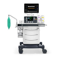
A9
Mindray A9 Manuals
Manuals and User Guides for Mindray A9. We have
2
Mindray A9 manuals available for free PDF download: Service Manual, Operating Instructions Manual
Mindray A9 Service Manual (424 pages)
Anesthesia System
Brand:
Mindray
| Category:
Medical Equipment
| Size: 20.37 MB
Table of Contents
Intellectual Property Statement
3
Revision History
3
Preface
4
Manual Purpose
4
Table of Contents
5
Safety
15
Safety Information
15
Warnings
15
Cautions
22
Notes
26
Theory of Operation
29
System Overview
29
Introduction
29
Appearance
31
Labels
43
Acronyms and Abbreviations
47
Subsystems
50
Electrical Circuit
50
Power System
53
Display System
56
Monitoring System
60
EFCS Flowmeter System
63
Auxiliary O2/Air System
66
Electronic Vaporizer System (A9)
72
Other Parts
72
Pneumatic Part
80
Symbols
87
Gas Supply Subsystem
87
Flowmeter Subsystem
94
Vaporizer Subsystem
95
Breathing Subsystem
100
Auxiliary Gas Supply Subsystem
107
AGSS Subsystem
108
Negative Pressure Suction Subsystem
112
Installation Guide
115
Preparations
115
Accessories
115
Tools
115
Installation Procedure
115
Unpacking
116
Installation
119
Tests after Installation
126
Maintenance Period
127
Pre-Maintenance Check
127
Parts of the Maintenance Packages
127
Installation Positions of the Sealing Rings and Filters in the Maintenance Packages
127
Maintenance Report
132
Testing
133
Power-On Self-Test
133
Performing the Power-On Self-Test
133
Power-On Self-Test Alarm Messages
133
System Check
134
Performing the System Check
135
Gas Supply Tests
136
O2 Supply Test
136
N2O Supply Test
136
AIR Supply Test
136
Cylinder Supply Tests
137
N2O Cylinder Supply Test
137
O2 Cylinder Supply Test
137
AIR Cylinder Supply Test
138
EFCS Accuracy Test
138
BFCS Function Tests
139
Checking Needle Valve Correspondence
139
Checking Needle Valve Not Closed
139
Accuracy Confirmation Test
140
Electronic Vaporizer Test (A9 Only)
140
Vaporizer Monitoring Function Test
140
Vaporizer Self-Locking Test
141
Vaporizer Interlock Test
141
Vaporizer Accuracy Test
142
Mechanical Vaporizer Test (A8 Only)
143
Vaporizer Interlock Test
143
Vaporizer Back Pressure Test
143
Vaporizer Accuracy Test
143
Vaporizer Leak Test
144
Other Functional Tests
145
High-Flow O2 Supply Test
145
High-Pressure O2 Output Test
145
O2 Flush Test
146
Mechanical ACGO Function Test
146
Internal AG Module Test
146
Circuit Function Tests
147
O2 Concentration and Tidal Volume Test
147
APL Valve Test
147
Patient Circuit Heating Test
148
Sample Gas Return Test
148
Active AGSS Check
148
Negative Pressure Suction Tests
149
Alarm Tests
149
Power Failure Alarm Test
149
Breathing Circuit Alarm Tests
149
O2 Supply Failure and Balance Gas Branch Flow Not Achieved Alarm Tests5-18
150
Ventilator-Related Alarm Tests
151
System Ventilation Performance Tests
153
Manual Mode Ventilation Test
153
VCV Adult Ventilation Mode Test
153
VCV Pediatric Ventilation Mode Test
154
PCV Adult Ventilation Mode Test
155
Sensor Zero Point Check
155
Constant Flow Test (Checking the Flow Sensor Accuracy)
156
Constant Flow Test (Checking the Pressure Sensor Accuracy)
157
Electrical Tests
159
Auxiliary Power Receptacle Test
159
Work Light Test
159
Electrical Safety Inspection Test
160
System Calibration
163
Overview
163
Precautions
163
Warnings
163
Cautions
164
Notes
164
System Calibration
165
Flow Calibration (User)
167
O2 Sensor Calibration (User)
174
Flowmeter Zeroing (User)
182
High-Flow O2 Supply Zeroing (User)
185
Pressure Calibration (Service)
189
Expiratory Valve Calibration (Service)
201
Pressure and Flow Zeroing (Service)
205
Total Flow Sensor Calibration (Service)
208
Internal AG Calibration (User)
213
External AG Calibration (User)
214
NMT Sensor Check (User) (Canada Only)
215
Vaporizer Injector Calibration (Service) (A9 Only)
218
Tests after Calibration
224
Troubleshooting
225
Precautions
225
Power-On Troubleshooting
225
Power-On and Display Failures
225
Auxiliary Outlet Failures
226
Leak Test Failures in Auto Mode
226
Leak Test Failures in Manual Mode
228
Technical Alarms
229
Power-On Self-Test Alarms
229
CPU Board Runtime Alarms
235
Power Board Runtime Alarms
236
Electronic Flowmeter and BFCS Runtime Alarms
239
VCM Runtime Alarms
244
Electronic Vaporizer Runtime Alarms
251
AGSS Module Runtime Alarms
255
Auxiliary O2/Air Module Runtime Alarms
255
HFNC Module Runtime Alarms
256
External AG Module Runtime Alarms
256
Internal AG Module Runtime Alarms
260
BIS Module Runtime Alarms
261
CO2 Module Runtime Alarms
265
NMT Module Runtime Alarms
268
Typical Troubleshooting
270
Failure to Exit the Standby Mode
270
Auto/Manual Switchover Failure
270
Mechanical Ventilation Stop
271
Inaccurate Tidal Volume Control
271
Inaccurate Airway Pressure Control
272
Inaccurate PEEP Control
273
Irregular Flow Waveforms
274
BFCS Failures
275
Electronic Vaporizer Failures
276
AGSS Failures
278
Auxiliary O2/Air and HFNC Module Failures
279
After-Service Tests
281
Diagnostic Tests
281
Valves Test
281
Insp Valve Test
286
PEEP Valve Test
287
Safety Valve Test
288
FCS Tests
289
Vaporizer Tests (A9)
293
HFNC Test
299
Repair and Disassembly
301
Disassemble the O2 Cell Holder Assembly
301
Prepare for Disassembly
301
Remove the O2 Cell Holder Assembly
301
Disassemble the Sodalime Absorber Canister Assembly
301
Remove the Sodalime Absorber Canister Assembly
302
Disassemble the Bypass Assembly
302
Prepare for Disassembly
302
Remove the Bypass Assembly
302
Disassemble the Bag Arm Assembly
303
Prepare for Disassembly
303
Remove the Bag Arm Assembly
303
Disassemble the Patient Circuit Assembly
303
Remove the Patient Circuit Assembly
304
Disassemble the APL Valve Assembly
304
Prepare for Disassembly
304
Remove the APL Valve Assembly
304
Disassemble the Locking Nuts of the Inspiration and Expiration Connectors
305
Prepare for Disassembly
305
Remove the Locking Nuts of the Inspiration and Expiration Connectors
305
Disassemble the Inspiration and Expiration Connectors
306
Prepare for Disassembly
306
Remove the Inspiration and Expiration Connectors
306
Disassemble the Water Collection Cup
306
Remove the Water Collection Cup
306
Disassemble the Volume Exchanger Assembly
307
Prepare for Disassembly
307
Remove the Volume Exchanger Assembly
307
Disassemble the VE Box Assembly
307
Remove the VE Box Assembly
308
Disassemble the VE Mounting Box In-Position Switch
308
Prepare for Disassembly
308
Remove the VE Mounting Box In-Position Switch
309
Pre-Disassembly (Disassemble Housings and some System Parts)
309
Open the Service Door
309
Remove the Auxiliary Output Assembly
309
Remove the Rear Cover Plate of the Work Surface
310
Remove the Work Surface Cover Plate FRU
310
Remove the Instrument Panel Assembly
310
Remove the Upper-Left Cover Plate
311
Remove the Display Assembly
312
Disassemble the N2O, Air, and O2 Inlet Assemblies
312
Prepare for Disassembly
312
Remove the N2O, Air, and O2 Inlet Assemblies
313
Disassemble the Pipeline Negative Pressure Inlet Assembly
313
Prepare for Disassembly
313
Remove the Pipeline Negative Pressure Inlet Assembly
314
Disassemble the Pressure Switch (Gas Inlet)
314
Prepare for Disassembly
314
Remove the Pressure Switch (Gas Inlet)
315
Disassemble the I/O Interface Board
315
Prepare for Disassembly
315
Remove the I/O Interface Board
315
Disassemble the Monitoring Board
316
Prepare for Disassembly
316
Remove the Monitoring Board
316
Disassemble the AC-DC Board
317
Prepare for Disassembly
317
Remove the AC-DC Board
317
Disassemble the DC-DC Board
318
Prepare for Disassembly
318
Remove the DC-DC Board
318
Disassemble the Motherboard
319
Prepare for Disassembly
319
Pre-Disassembly
319
Remove the Motherboard FRU
319
Disassemble the Pressure Regulator Assembly (0645)
320
Prepare for Disassembly
320
Remove the Pressure Regulator Assembly (0645)
320
Disassemble the EFCS Flowmeter Monitoring Board
320
Remove the EFCS Flowmeter Monitoring Board
321
Disassemble the EFCS Flowmeter FRU (O2/N2O/Air)
321
Prepare for Disassembly
321
Remove the EFCS Flowmeter FRU (O2/N2O/Air)
321
Disassemble the EFCS Flowmeter Flow Sensors
322
Prepare for Disassembly
322
Remove the EFCS Flowmeter Flow Sensors
322
Disassemble the N2O, Air, and O2 Cylinder Yoke Assemblies
323
Prepare for Disassembly
323
Remove the N2O, Air, and O2 Cylinder Yoke Assemblies
324
Disassemble the Sensor Adapter Board PCBA
324
Prepare for Disassembly
324
Remove the Sensor Adapter Board PCBA
325
Disassemble the High-Flow O2 Supply Assembly or Auxiliary O2/Air Assembly
325
Prepare for Disassembly
325
Remove the High-Flow O2 Supply Assembly or Auxiliary O2/Air Assembly8-26
326
Disassemble the System Switch Assembly
326
Prepare for Disassembly
326
Remove the System Switch Assembly
327
Disassemble the High-Flow O2 Therapy Flowmeter or Auxiliary Output Flowmeter Assembly
327
Prepare for Disassembly
327
Remove the High-Flow O2 Therapy Flowmeter or Auxiliary Output Flowmeter Assembly
328
Disassemble the Upper-Half Drawer Assembly
328
Prepare for Disassembly
328
Remove the Upper-Middle Drawer Assembly
328
Disassemble the Lower Drawer Assembly
329
Prepare for Disassembly
329
Remove the Lower Drawer Assembly
329
Disassemble the CO2 Locking Assembly
330
Prepare for Disassembly
330
Remove the CO2 Locking Assembly
330
Disassemble the AGSS Assembly
331
Prepare for Disassembly
331
Remove the AGSS Assembly
331
Disassemble the Module Rack Assembly
332
Prepare for Disassembly
332
Remove the Module Rack Assembly
332
Disassemble the Battery Box Assembly
333
Prepare for Disassembly
333
Remove the Battery Box Assembly
333
Disassemble the Anesthesia Calculation Pipeline Assembly
334
Prepare for Disassembly
334
Remove the Anesthesia Calculation Pipeline Assembly
334
Disassemble the Drive Gas Assembly
334
Remove the Drive Gas Assembly
335
Disassemble the ACGO Assembly
335
Prepare for Disassembly
335
Remove the ACGO Assembly
335
Disassemble the O2 Cell Calibration Valve Assembly
336
Prepare for Disassembly
336
Remove the O2 Cell Calibration Valve Assembly
336
Disassemble the Air Filter
337
Prepare for Disassembly
337
Remove the Air Filter
337
Disassemble the AG Module
337
Remove the AG Module
338
Disassemble the Valve Cover
338
Prepare for Disassembly
338
Remove the Valve Cover Assembly
338
Disassemble the One-Way Valve
339
Prepare for Disassembly
339
Remove the One-Way Valve
339
Disassemble the Vaporizer Manifold Assembly (A9)
339
Remove the Vaporizer Manifold Assembly
340
Disassemble the Electronic Vaporizer Base Interface Board PCBA (A9)
341
Prepare for Disassembly
341
Remove the Electronic Vaporizer Base Interface Board PCBA
341
Disassemble the O-Ring of Gas Connector (A9)
341
Remove the O-Ring of Gas Connector (A9)
342
Disassemble the Pneumatically-Controlled Lock Assemblies (A9)
342
Prepare for Disassembly
342
Remove the Pneumatically-Controlled Lock Assemblies
343
Disassemble the Small-Screen CPU Board (Without the Display Cable)
343
Prepare for Disassembly
343
Remove the Small-Display CPU Board Assembly (Without the Display Cable)8-44
344
Disassemble the Small Display
344
Prepare for Disassembly
344
Remove the Small Display Assembly
345
Disassemble the Backup Flowmeter Assembly
346
Prepare for Disassembly
346
Remove the Backup Flowmeter Assembly
346
Disassemble the Backup Flowmeter Door Electromagnet
347
Prepare for Disassembly
347
Remove the Backup Flowmeter Door Electromagnet
348
Disassemble the Indicator Light Board
348
Prepare for Disassembly
348
Remove the Indicator Light Board
348
Disassemble the Segment Display
349
Prepare for Disassembly
349
Remove the Segment Display
349
Disassemble the Encoder Beside the Segment Display
350
Prepare for Disassembly
350
Remove the Encoder Beside the Segment Display
350
Disassemble the BFCS Switch Control Board
351
Prepare for Disassembly
351
Remove the BFCS Switch Control Board
352
Disassemble the BFCS Door Assembly
352
Prepare for Disassembly
352
Remove the BFCS Door Assembly
352
Disassemble the Backup Flowmeter Keyboard
353
Prepare for Disassembly
353
Remove the Backup Flowmeter Keyboard
353
Disassemble the Alarm Lamp Board
354
Prepare for Disassembly
354
Removing the Alarm Lamp Board
354
Disassemble the Speaker
354
Remove the Speaker
355
Disassemble the Display Service Kit
355
Prepare for Disassembly
355
Remove the Display Service Kit
355
Disassemble the CPU Board PCBA
355
Remove the CPU Board PCBA
356
Disassemble the Key Lighting Board
356
Prepare for Disassembly
356
Remove the Key Lighting Board
356
Disassemble the Encoder Knob (Top Hat-Shaped)
357
Prepare for Disassembly
357
Remove the Encoder Knob (Top Hat-Shaped)
357
Disassemble the Flow Regulator Encoder and Two Gas Knobs
358
Prepare for Disassembly
358
Remove the Flow Regulator Encoder and Two Gas Knobs
358
Disassemble the Airway Pressure Gauge
358
Remove the Airway Pressure Gauge
359
Disassemble the Auto/Manual Switch Assembly
359
Prepare for Disassembly
359
Remove the Auto/Manual Switch Assembly
360
Disassemble the Upper-Left Cover Plate FRU
360
Prepare for Disassembly
360
Remove the Upper-Left Cover Plate FRU
361
Disassemble the O2 Cell Door Cover Assembly
361
Prepare for Disassembly
361
Remove the O2 Cell Door Cover Assembly
362
Disassemble the O2 Cell Cable
362
Prepare for Disassembly
362
Remove the O2 Cell Cable
362
Disassemble the Circuit Adapter Block Assembly
363
Prepare for Disassembly
363
Remove the Circuit Adapter Block Assembly
363
Disassemble the Circuit Switch (Hook Lock)
364
Prepare for Disassembly
364
Remove the Circuit Switch (Hook Lock)
364
Disassemble the Circuit Heater
365
Prepare for Disassembly
365
Remove the Circuit Heater
365
Disassemble the Auto/Manual Position Detection Switch
366
Prepare for Disassembly
366
Remove the Auto/Manual Position Detection Switch
366
Disassemble the APL Valve Mounting Base Assembly
367
Prepare for Disassembly
367
Remove the APL Valve Mounting Base Assembly
367
Disassemble the Auto/Manual Drive Valve Assembly
368
Prepare for Disassembly
368
Remove the Auto/Manual Drive Valve Assembly
368
Disassemble the STEINCO 5-Inch Central Control Caster
368
Remove the STEINCO 5-Inch Central Control Caster
369
Disassemble the STEINCO 5-Inch Standalone Brake Casters
372
Prepare for Disassembly
372
Remove the STEINCO 5-Inch Standalone Brake Casters
373
Software Upload
375
Preparations
376
Upgrading the Software
377
Upgrade Via USB Drive
380
Test after Upgrade
380
Software Function Activation
381
Application of Software Function Activation Codes
381
Activation Procedure
382
Frus
385
Mechanical Subsystem
385
Display Assembly
385
Cylinder Yoke Assembly
387
High-Flow O2 Therapy Flowmeter Assembly, and System Switch Assembly11-4
388
High-Flow O2 Supply Assembly, Anesthesia Calculation Inlet Pipeline Assembly, and EFCS Flowmeter Service Part
389
Instrument Panel Assembly
390
O2 Cell Door Cover Assembly, O2 Cell Calibration Valve Assembly, and ACGO Assembly
392
Built-In AG Assembly (A9)
393
Gas Inlet Assembly
394
Drawer and Battery Box Assemblies
396
Circuit Adapter Block Assembly
397
Boards
398
Work Surface and Left Cover Plate
399
Mechanical Vaporizer Subsystem (A8)
401
AGSS Assembly
402
VE Mounting Box Assembly
403
Sensor Adapter Board PCBA
404
Drive Gas Assembly
409
Gas Supply Subsystem
410
O2 Inlet Assembly
410
Flowmeter Subsystem
411
EFCS Assembly
411
Vaporizer Subsystem(A9)
412
Electronic Vaporizer Base
412
Breathing Circuit Subsystem
413
Patient Circuit Material Package
413
Patient Circuit Assembly
414
Circuit Connector Adapter Assembly
415
A Tube Connection Diagrams
417
Advertisement
Mindray A9 Operating Instructions Manual (288 pages)
Anesthesia System
Brand:
Mindray
| Category:
Medical Equipment
| Size: 6.66 MB
Table of Contents
Table of Contents
5
Safety
17
Safety Information
18
Warnings
18
Cautions
23
Notes
26
Symbols
27
Product Description
33
Introduction
34
Indications for Use
34
Structure and Composition
34
Functions and Features
34
Equipment Views
36
Main Unit (Front View)
36
Main Unit (Rear View)
39
Main Unit (Left View)
41
Main Unit (Right View)
43
Main Unit (Top View)
44
Breathing System
45
Negative Pressure Suction Device
46
Installation and Disassembly
47
Breathing System
49
Initial Setup
49
Unpacking
49
Vaporizer
50
Filling and Draining the Vaporizer
51
Negative Pressure Suction Device
51
Turn off Negative Pressure Suction Device
52
Turn on Negative Pressure Suction Device
52
High-Flow Nasal Cannula Oxygen (HFNC) Tube
53
Active AGSS
54
Anesthetic Gas Scavenging System (AGSS)
54
Passive AGSS
55
Connect Anesthesia System with Information System
57
Connect Anesthesia System with Information System through Ethernet
57
Connect Anesthesia System with Information System through Serial Interface
57
Connect Anesthesia System to Patient Monitor
58
Connect Anesthesia System to Patient Monitor through Serial Interface
58
Connect Anesthesia System with Egateway
58
System Interface
59
Main Screen
60
System Interface
60
Patient Information
61
System Information Title
61
Retrieve Patient Information from ADT Server
63
Set Patient Information in Anesthesia System
63
Synchronize Patient Information
63
Timer (Elapsed Timer/Countdown Timer)
64
Alarm and Prompt Message
65
Audio Pause/Alarm Reset Icon
65
Date and Time
66
Screen Brightness
66
Volume
66
Battery Status
67
Electronic Flow Control System
68
Fresh Gas Flow Display
68
Total Flow Control Mode
69
Direct Flow Control Mode
70
Optimizer
71
Backup Flow Control System
73
Waveform/Parameter/Spirometry/Trend Display Zone
73
Spirometry Screen
75
Waveform/Parameter Screen
75
Loop Type
76
Show Reference
76
Review Loops
77
Save Loop
77
Mini Trends Screen
78
Compl/Peep Trend Screen
79
System Soft Key
80
Ventilation Mode Tabs
80
History
81
List Trends
81
Graphic Trends
82
Event Log
83
Screen
83
Export
84
Flow Pause
84
Lung Recruitment (Optional)
84
Alarm Reset
85
Alarms
85
Audio Pause
85
Cardiac Bypass Mode
85
Screens
85
Setup Menu
85
Ventilation
86
AG Settings (AG Module Configured)
88
Information
88
Oxygen (O2)
88
Screen
90
Export System Data
91
Calibrate
92
System
92
Setup
94
Profiles
97
Network
99
Information
102
Service Tab
102
Automatic Ventilation, Flow Pause or Bypass
103
Gas Supply Pressure Monitoring
103
Manual Ventilation
103
Status Screen
103
Volume Exchanger
103
Agss
104
Preoperative Tests
105
Requirements of Preoperative Tests
106
Introduction
107
Preoperative Checklist
107
Suggested Preoperative Checklist
107
Inspect the System
109
Auto System Check
110
System Check
110
Leak & Compliance Test
111
N 2 O Pipeline Test
111
O 2 Pipeline Test
111
Pipeline Test
111
Power Failure Alarm Test
111
Air Pipeline Test
112
Basic Ventilation Test
112
Backup Gas Cylinder Test
113
Check Cylinder Pressure
113
High Pressure Leak Test of N O Cylinders
113
High Pressure Leak Test of O Cylinders
113
Flow Control System Test
114
High Pressure Leak Test of Air Cylinders
114
Vaporizer Back Pressure Test
116
Vaporizer Leak Test
116
Vaporizer Test
116
APL Valve Test
117
Breathing System Test
117
Inspiratory and Expiratory Check Valve Tests
117
Alarm Test
118
O 2 Concentration Monitoring and Alarm Test
118
Prepare for Alarm Tests
118
Apnea Alarm Test
119
Minute Volume (MV) too Low Alarm Test
119
AG Module Alarm Test
120
Airway Pressure (Paw) too High Alarm Test
120
Airway Pressure (Paw) too Low Alarm Test
120
Continuous Airway Pressure too High Alarm Test
120
Check Passive AGSS
121
Inspect the AGSS
121
Inspect the Negative Pressure Suction Device
121
Pre-Operation Preparations
121
Operations
123
Powering off the Anesthesia System
124
Powering on the Anesthesia System
124
Enter Standby Mode
125
Patient Setup
125
Standby Mode
125
Exit Standby Mode
126
O 2 Sensor Calibration
126
Set Fresh Gas
126
Set O O and Air Inputs
126
Set Patient Information
126
Set Ventilation
127
Other Features
139
Start Automatic Ventilation
142
Relationships of Ventilation Parameters
143
Stop Automatic Ventilation
143
Anesthetic Gases and O Concentration Monitoring
145
Introduction
146
MAC Values
147
Agent Consumption Speed
148
Agent Usage Calculation
148
Identify External AG Module
149
AG Measurement Preparation
150
AG Module Settings
151
Measurement Limits
153
Sample Gas Recirculation
154
Troubleshooting
154
Calibrate the AG Module
155
Alarms and Messages
157
Introduction
158
Alarm Display
160
Setting Alarm Volume
162
Pause Alarm Audio
163
Setting Alarm Limits
164
View Active Alarms
167
Alarms and Prompt Messages
168
Maintenance
187
Breathing System Service
189
Maintenance Schedule
189
Flow Sensor Calibration
190
O 2 Sensor Calibration
190
Electrical Safety Inspection
193
Handling of Gathered Water
193
Cleaning and Disinfection
194
Periodic Maintenance
215
Product Specifications
217
Physical Specifications
220
Safety Designations
220
Electrical Specifications
222
Environmental Specifications
222
Pneumatic Specifications
224
Breathing System Specifications
226
Anesthetic Gas Scavenging System (AGSS)
230
Negative Pressure Suction Device
230
Monitor Module
231
Ventilator Specifications
237
Displays and Controls Specifications
240
Alarms
241
Response Time of the Anesthesia System to an Increase in O2 Concentration (from 21% to 90%/100%)
242
Parameters and Factory Defaults
247
Limits
248
Spirometry Screen
248
Main Menu
249
Fresh Gas Control
252
History
252
Lung Recruitment
252
Screen Brightness
252
Volume
252
Patient Information
253
Ventilation Mode
253
Ventilation Linkage Parameters
256
Advertisement
Related Products
Mindray Accutorr V
Mindray A7
Mindray A3
Mindray A5
Mindray accutorr plus
Mindray A Series
Mindray Datascope AS 3000
Mindray A8
Mindray Anesus I9
Mindray Anesus I9 Easi
Mindray Categories
Medical Equipment
Diagnostic Equipment
Measuring Instruments
Monitor
Water Pump
More Mindray Manuals
Login
Sign In
OR
Sign in with Facebook
Sign in with Google
Upload manual
Upload from disk
Upload from URL