Sign In
Upload
Manuals
Brands
Miller Manuals
Welding System
Trailblazer 302 Diesel
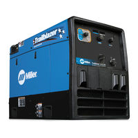
Miller Trailblazer 302 Diesel Manuals
Manuals and User Guides for Miller Trailblazer 302 Diesel. We have
6
Miller Trailblazer 302 Diesel manuals available for free PDF download: Technical Manual, Owner's Manual, Application Manual
Miller Trailblazer 302 Diesel Technical Manual (81 pages)
Brand:
Miller
| Category:
Welding System
| Size: 7.01 MB
Table of Contents
Table of Contents
4
Section 1 − Safety Precautions for Servicing
6
Symbol Usage
6
Servicing Hazards
6
California Proposition 65 Warnings
7
EMF Information
7
Section 2 − Definitions
8
Section 3 − Specifications
8
Weld, Power, and Engine Specifications
8
Section 4 − Installation
9
Installing Welding Generator
9
Dimensions, Weights, and Operating Angles
10
Installing Exhaust Pipe
10
Activating the Dry Charge Battery (if Applicable)
11
Connecting the Battery
11
Overview and Engine Prestart Checks
13
Connecting to Weld Output Terminals
15
Selecting Weld Cable Sizes
16
Remote Receptacle Information
16
Section 5 − Operating the Welding Generator
17
Engine Control Switches
17
Weld Output Controls
18
Process/Contactor Switch
19
Stick Start Procedure − Scratch Start Technique
20
TIG Lift-Arct Start Procedure
20
Ending the TIG Arc with Auto-Cratert and Auto-Stopt
21
Remote Amperage Control
22
Section 6 − Operating Auxiliary Equipment
23
Generator Power Receptacles
23
Simultaneous Weld and Power
24
Wiring Optional 240 Volt Plug
24
Section 7 − Maintenance
26
Routine Maintenance
26
Maintenance Label and Engine Maintenance Activities
27
Servicing Air Cleaner
29
Adjusting Engine Speed
30
Overload Protection
33
Section 8 − Theory of Operation
35
Section 9 − Troubleshooting
37
Troubleshooting Tables
37
Troubleshooting Circuit Diagram for Welding Generator (Use with Section 9-3)
43
Troubleshooting Values for Circuit Diagram (Use with Section 9-2)
45
Waveforms for Section
47
Power Board PC1 Testing Information
49
Power Board PC1 Test Point Values
50
Control Board PC2 Testing Information
52
Control Board PC2 Test Point Values
53
Replacing Brushes and Cleaning Slip Rings
55
Adjusting Wire (MIG) Weld Puddle Consistency (Units with Stabilizer Tabs)
56
Checking Unit Output after Servicing
57
Section 10 − Disassembly and Reassembly
58
Disassembly of Unit
58
Disassembly of Generator
59
Section 11 − Electrical Diagrams
60
Section 12 − Run-In and Wetstacking
66
Run-In and Wetstacking
66
Section 13 − Performance Data
67
Fuel Consumption Curves
67
Generator Power Curve
68
Duty Cycle
68
Stick Mode Volt-Ampere Curves
69
TIG Mode Volt-Ampere Curves
70
MIG Mode Volt-Ampere Curve
71
Section 14 − Parts Eff W/Lf314257 and Following
73
Advertisement
Miller Trailblazer 302 Diesel Owner's Manual (68 pages)
Brand:
Miller
| Category:
Welding System
| Size: 2.43 MB
Table of Contents
Table of Contents
3
Section 1 − Safety Precautions − Read before Using
5
Symbol Usage
5
Arc Welding Hazards
5
Engine Hazards
7
Compressed Air Hazards
7
Additional Symbols for Installation, Operation, and Maintenance
8
California Proposition 65 Warnings
10
Principal Safety Standards
10
EMF Information
10
Section 2 − Consignes de Sécurité − Lire Avant Utilisation
11
Signification des Symboles
11
Dangers Relatifs Au Soudage À L'arc
11
Dangers Existant en Relation Avec Le Moteur
13
Dangers Liés À L'air Comprimé
14
Dangers Supplémentaires en Relation Avec L'installation, Le Fonctionnement Et la Maintenance
15
Proposition Californienne 65 Avertissements
17
Principales Normes de Sécurité
17
Informations Relatives Aux CEM
17
Section 3 − Definitions
18
Symbol Definitions
18
Section 4 − Specifications
19
Weld, Power, and Carbureted Engine Specifications (Subaru EH65, Kohler CH-23)
19
Weld, Power, and EFI Engine Specifications (Kohler ECH-730)
19
Dimensions, Weights, and Operating Angles
20
Fuel Consumption Curves
21
Generator Power Curve
22
Duty Cycle
22
Stick and MIG Mode Volt-Ampere Curves
23
TIG Mode Volt-Ampere Curves
24
Section 5 − Installation
25
Serial Number and Rating Label Location
25
Installing Welding Generator
25
Grounding Generator to Truck or Trailer Frame
26
Installing Exhaust Pipe
26
Engine Prestart Checks (Kohler-Powered Units)
27
Engine Prestart Checks (Subaru-Powered Units)
28
Connecting or Replacing the Battery
29
Electronic Fuel Injection (EFI) System and Battery Information
29
Weld Output Terminals
30
Connecting to Weld Output Terminals
31
Selecting Weld Cable Sizes
31
Remote Receptacle Information
32
Section 6 − Operating Welding Generator
34
Front Panel Controls (See Section 6-2)
34
Description of Front Panel Controls (See Section 6-1)
35
Cold Weather Engine Operation
35
Process/Contactor Switch on AC/DC Models
36
Stick Start Procedure − Scratch Start Technique
37
Lift-Arct TIG with Auto-Cratert and Auto-Stopt
38
Remote Voltage/Amperage Control
39
Section 7 − Operating Auxiliary Equipment
40
Generator Power Receptacles and Supplementary Protectors
40
Optional GFCI Receptacles
40
Simultaneous Weld and Power
41
Wiring Instructions for Optional 240 Volt, Single-Phase Plug (NEMA 14-50P)
41
Section 8 − Maintenance & Troubleshooting
42
Maintenance Label
42
Routine Maintenance
43
Electronic Fuel Injection (EFI) System and Servicing Information
43
Servicing Optional Spark Arrestor
44
Servicing Air Cleaner
44
Changing Engine Oil, Oil Filter, and Fuel Filter (Kohler-Powered Units)
45
Changing Engine Oil, Oil Filter, and Fuel Filter (Subaru-Powered Units)
46
Adjusting Engine Speed (Kohler Carbureted Units [CH-23])
47
Adjusting Engine Speed (Kohler EFI Units [ECH-730])
48
Adjusting Engine Speed (Subaru-Powered Units)
49
Overload Protection
50
Welding Troubleshooting
51
Generator Power Troubleshooting
52
Engine Troubleshooting
52
Section 9 − Parts List
54
Recommended Spare Parts
54
Section 10 − Electrical Diagrams
56
Section 11 − Generator Power Guidelines
60
Miller Trailblazer 302 Diesel Owner's Manual (68 pages)
Diesel Engine Driven Welder / Generator
Brand:
Miller
| Category:
Welding System
| Size: 2.54 MB
Table of Contents
Table of Contents
3
Section 1 − Safety Precautions − Read before Using
5
Symbol Usage
5
Arc Welding Hazards
5
Engine Hazards
7
Hydraulic Hazards
8
Compressed Air Hazards
8
Additional Symbols for Installation, Operation, and Maintenance
9
California Proposition 65 Warnings
10
Principal Safety Standards
11
EMF Information
11
Section 2 − Consignes de Sécurité − Lire Avant Utilisation
12
Signification des Symboles
12
Dangers Relatifs Au Soudage À L'arc
12
Dangers Existant en Relation Avec Le Moteur
14
Dangers Liés À L'hydraulique
15
Dangers Liés À L'air Comprimé
16
Dangers Supplémentaires en Relation Avec L'installation, Le Fonctionnement Et la Maintenance
17
Proposition Californienne 65 Avertissements
18
Principales Normes de Sécurité
19
Informations Relatives Aux CEM
19
Section 3 − Definitions
20
Section 4 − Specifications
20
Weld, Power, and Engine Specifications
20
Dimensions, Weights, and Operating Angles
21
Section 5 − Installation
22
Serial Number and Rating Label Location
22
Installing Welding Generator
22
Grounding Generator to Truck or Trailer Frame
23
Installing Exhaust Pipe
23
Connecting the Battery
24
Overview and Engine Prestart Checks
26
Weld Output Terminals
28
Connecting to Weld Output Terminals
28
Selecting Weld Cable Sizes
29
Remote Receptacle Information
29
Section 6 − Operating the Welding Generator
30
Engine Control Switches
30
Weld Output Controls
31
Process/Contactor Switch
32
Stick Start Procedure − Scratch Start Technique
33
Lift-Arct TIG with Auto-Cratert and Auto-Stopt
34
Remote Amperage Control
35
Section 7 − Operating Auxiliary Equipment
36
Generator Power Receptacles
36
Simultaneous Weld and Power
37
Wiring Optional 240 Volt Plug
37
Section 8 − Maintenance and Troubleshooting
38
Routine Maintenance
38
Servicing Air Cleaner
39
Maintenance Label and Engine Maintenance Activities
40
Adjusting Engine Speed
42
Overload Protection
45
Troubleshooting Tables
46
Section 9 − Parts List
49
Recommended Spare Parts
49
Circuit Diagram for Welding Generator
50
Section 10 − Electrical Diagrams
50
Section 11 − Run-In and Wetstacking
52
Run-In and Wetstacking
52
Section 12 − Performance Data
53
Fuel Consumption Curves
53
Generator Power Curve
54
Duty Cycle
54
Stick Mode Volt-Ampere Curves
55
TIG Mode Volt-Ampere Curves
56
MIG Mode Volt-Ampere Curve
57
Section 13 − Generator Power Guidelines
58
Grounding When Supplying Building Systems
59
Advertisement
Miller Trailblazer 302 Diesel Owner's Manual (65 pages)
Brand:
Miller
| Category:
Inverter
| Size: 3.5 MB
Table of Contents
Section 1 − Safety Precautions − Read before Using
5
Engine Hazards
6
Compressed Air Hazards
7
California Proposition 65 Warnings
8
Signification des Symboles
9
Dangers Existant en Relation Avec Le Moteur
10
Dangers Liés À L'air Comprimé
11
Proposition Californienne 65 Avertissements
12
Section 3 − Definitions
14
Section 5 − Installation
15
Dimensions, Weights, and Operating Angles
16
Activating the Dry Charge Battery (if Applicable)
17
Overview and Engine Prestart Checks
18
Connecting to Weld Output Terminals
20
Selecting Weld Cable Sizes
21
Adjusting Wire (MIG) Weld Puddle Consistency
22
Section 6 − Operating the Welding Generator
23
Weld Output Controls
24
Process/Contactor Switch
25
Stick Start Procedure − Scratch Start Technique
26
Remote Amperage Control
27
Section 7 − Operating Auxiliary Equipment
28
Wiring Instructions for Optional 240 Volt, Single-Phase Plug (NEMA 14-50P)
29
Section 8 − Maintenance and Troubleshooting
31
Maintenance Label and Engine Maintenance Activities
32
Servicing Air Cleaner
34
Adjusting Engine Speed
35
Overload Protection
38
Troubleshooting Tables
39
Recommended Spare Parts
42
Section 9 − Electrical Diagrams
44
Section 10 − Run-In and Wetstacking
46
Section 11 − Performance Data
47
Generator Power Curve
48
Stick Mode Volt-Ampere Curves
49
TIG Mode Volt-Ampere Curves
50
MIG Mode Volt-Ampere Curve
51
Section 12 − Generator Power Guidelines
52
Miller Trailblazer 302 Diesel Owner's Manual (40 pages)
Brand:
Miller
| Category:
Welding System
| Size: 0.73 MB
Table of Contents
Table of Contents
3
Section 1 − Safety Precautions - Read before Using
7
Symbol Usage
7
Arc Welding Hazards
7
Additional Symbols for Installation, Operation, and Maintenance
9
California Proposition 65 Warnings
10
Principal Safety Standards
10
EMF Information
10
Additional Safety Symbols and Definitions
15
Section 3 − Specifications
18
Serial Number and Rating Label Location
18
Specifications
18
Environmental Specifications
18
Duty Cycle and Overheating
20
Volt-Ampere Curves
20
Section 4 − Installation
21
Selecting a Location
21
Dimensions and Weights
22
115 VAC Receptacle and Supplementary Protectors
22
Selecting Cable Sizes
23
Weld Output Terminals
23
Connecting Weld Output Cables
24
Remote 14 Receptacle RC8
24
Remote 14 Receptacle RC8 Information
25
Electrical Service Guide
26
Placing Jumper Links
27
Connecting 3-Phase Input Power
28
Section 5 − Operation
30
Controls (Non CE Models)
30
Controls (CE Models)
30
Section 6 − Maintenance & Troubleshooting
31
Routine Maintenance
31
Fuse F1
31
Short Circuit Shutdown
31
Troubleshooting Table
32
Section 7 − Parts List
32
Recommended Spare Parts
32
Section 8 − Electrical Diagram
34
Miller Trailblazer 302 Diesel Application Manual (16 pages)
Generator Power
Brand:
Miller
| Category:
Inverter
| Size: 0.58 MB
Table of Contents
Table of Contents
3
Safety
5
How Much Generator Power Do You Need
6
Wattage Reference Guide
7
Frequently Asked Questions
8
Grounding Generator to Truck or Trailer Frame
9
Selecting Auxiliary Equipment
9
Grounding When Supplying Building Systems
10
How Much Power Can the Generator Supply
11
Power Required to Start a Motor
11
Typical Connections to Supply Standby Power
12
Wiring Optional 240 Volt, Single-Phase Plug (NEMA 14-50P)
13
Selecting Extension Cord (Use Shortest Cord Possible)
14
Advertisement
Related Products
Miller TRAILBLAZER 302 AIR PAK
Miller Big Blue 302D
Miller Gold Star 300SS
Miller Trailblazer 301 D
Miller 3045 FC
Miller 301182
Miller 301183
Miller 300617001
Miller 300360001
Miller 300618003
Miller Categories
Welding System
Welding Accessories
Camera Accessories
Portable Generator
Motorcycle Accessories
More Miller Manuals
Login
Sign In
OR
Sign in with Facebook
Sign in with Google
Upload manual
Upload from disk
Upload from URL