Sign In
Upload
Manuals
Brands
Miller Manuals
Welding System
Millermatic 350P
Miller Millermatic 350P Manuals
Manuals and User Guides for Miller Millermatic 350P. We have
3
Miller Millermatic 350P manuals available for free PDF download: Technical Manual, Owner's Manual
Miller Millermatic 350P Technical Manual (136 pages)
Arc Welding Power Source and Wire Feeder
Brand:
Miller
| Category:
Welding System
| Size: 4.33 MB
Table of Contents
Table of Contents
3
Section 1 − Safety Precautions for Servicing
5
Symbol Usage
5
Servicing Hazards
5
California Proposition 65 Warnings
6
EMF Information
6
Section 2 − Introduction
7
Serial Number and Rating Label Location
7
Selecting a Location
7
Section 3 − Specifications
8
Specifications
8
Duty Cycle and Overheating
8
Volt-Ampere Curve
9
Weld Output Terminals and Selecting Cable Sizes
10
Connecting to Weld Output Terminals
11
Section 4 − Installation
12
Installing Work Clamp
12
Installing Welding Gun/Cable Holder
12
Installing Welding Gun
13
Connecting Spoolmatic) 15A or 30A Gun
14
Connecting XR Edge, XR-A Gun, XR-A Python, or XR - Alumapro
15
Setting Gun Polarity for Wire Type
16
Installing Gas Supply
17
Installing Wire Spool and Adjusting Hub Tension
18
Electrical Service Guide
18
Selecting Input Voltage (200/230/460 Volt Models Only)
19
Connecting 3-Phase Input Power
20
Connecting 1-Phase Input Power
21
Threading Welding Wire for MIG Gun
22
Threading Welding Wire for XR Edge, XR-A Gun, XR-A Python, or XR - Alumapro
23
Threading Welding Wire through XR Guns
24
Section 5 − Operation
25
Controls
25
MIG Mode
26
Jog Mode
26
Weld Status
26
MIG Gun-On-Demand
26
Pulse MIG Mode Voltage Adjustment
26
Pulse MIG Gun-On-Demand
26
Tip Saver
26
Weld Parameters for MIG Mode
28
Weld Parameters for Pulse Mode
29
Section 6 − Programming
30
MIG Welding Mode
30
Pulse MIG Welding Mode
31
Timers
32
Arc Times, Arc Starts, Hot Start, Set up Push/Pull Motor Torque (SUP) (Aluminum Pulse Only), and Crater Fill
33
Setting Hot Start (Aluminum Pulse Only) Parameters
34
Setting Crater Fill
35
Recommended Crater Fill Parameters
36
System Reset
38
Motor Calibration Function Prior to Serial No. LH170741B
39
Motor Calibration Function Eff W/Serial No. LH170741B
40
Set up Push Motor Torque (SUP)
41
Section 7 − Theory of Operation
42
Section 8 − Pre-Power Troubleshooting
46
Checking Unit before Applying Power
46
Measuring Input Capacitor Voltage (200/230/460 V Model Shown)
47
Output Diodes
48
Input Rectifier SR1, Input Capacitors C3 and C4, and Resistors R11 and R12
49
(200/230/460 V Model Shown)
49
IGBT Modules PM1, PM2 (200/230/460 V Model Shown)
50
Diodes D1 and D2 (200/230/460 V Model Shown)
51
Section 9 − Troubleshooting
52
Troubleshooting Table
52
Help Displays
54
Troubleshooting Circuit Diagram for 200/230/460/575 V Models
56
Waveforms for Sections
59
Main Control Board PC1 Testing Information (Prior to LE411272)
60
(Use with Section 9-6)
60
Main Control Board PC1 Test Point Values (Prior to LE411272)
61
Main Control Board PC1 Testing Information (Eff. W/Le411272)
64
(Use with Section 9-8)
64
Main Control Board PC1 Test Point Values (Eff. W/Le411272)
65
Interconnect Board PC2 Testing Information (200/230/460 V Model Shown)
68
(Use with Section 9-10)
68
Interconnect Board PC2 Test Point Values
69
User Interface Board PC3 Testing Information (Use with Section 9-12)
70
User Interface Board PC3 Test Point Values
71
Pulse/Tach Board PC6 Testing Information (Use with Section 9-14)
72
Pulse/Tach Board PC6 Test Point Values
73
Section 10 − Maintenance
74
Routine Maintenance
74
Additional Maintenance (if Necessary)
74
Overheating
74
Ground Clamp and Gun Connections
74
Changing Drive Roll and Wire Inlet Guide
75
Removing Fan Motor
76
Section 11 − Electrical Diagrams
77
SECTION 12 − PARTS LIST (Eff W/Lc447907 Thru LE443589)
94
SECTION 13 − PARTS LIST (Eff W/Le443590 Thru LJ420783B)
112
SECTION 14 − PARTS LIST (Eff W/Lj420783B and Following)
124
And Following)
124
Advertisement
Miller Millermatic 350P Owner's Manual (72 pages)
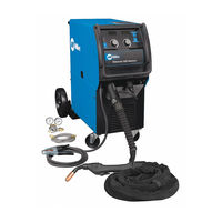
Millermatic 350 And Millermatic 350P with Roughneck 4012 Gun
Brand:
Miller
| Category:
Welding System
| Size: 3.16 MB
Table of Contents
Table of Contents
3
Section 1 − Safety Precautions - Read before Using
5
Symbol Usage
5
Arc Welding Hazards
5
Additional Symbols for Installation, Operation, and Maintenance
7
California Proposition 65 Warnings
7
Principal Safety Standards
8
EMF Information
8
Section 2 − Consignes de Sécurité − Lire Avant Utilisation
9
Symboles Utilisés
9
Dangers Relatifs Au Soudage À L'arc
9
Dangers Supplémentaires en Relation Avec L'installation, Le Fonctionnement Et la Maintenance
11
Proposition Californienne 65 Avertissements
11
Principales Normes de Sécurité
12
Information EMF
12
Section 3 − Installation
13
Specifications
13
Duty Cycle and Overheating
13
Volt-Ampere Curve
14
Connecting to Weld Output Terminals
14
Installing Work Clamp
15
Installing Welding Gun/Cable Holder
15
Installing Welding Gun
16
Connecting Spoolmatic) 15A or 30A Gun
17
Connecting XR Edge, XR-A Gun, or XR-A Python
18
Setting Gun Polarity for Wire Type
19
Installing Gas Supply
20
Installing Wire Spool and Adjusting Hub Tension
20
Electrical Service Guide
21
Selecting Input Voltage (200/230/460 Volt Models Only)
22
Selecting a Location and Connecting 3-Phase Input Power
23
Selection a Location and Connecting 1-Phase Input Power
24
Threading Welding Wire for Roughneck Gun
25
Threading Welding Wire for XR Edge, XR-A Gun, or XR-A Python
26
Threading Welding Wire through XR Guns
27
Section 4 − Operation
28
Controls
28
MIG Mode
28
Jog Mode
29
Weld Status
29
MIG Gun-On-Demand
29
Pulse MIG Mode Voltage Adjustment
29
Pulse MIG Gun-On-Demand
29
Tip Saver
29
Weld Parameters for MIG and Pulse Mode
30
Recommended Crater Fill Parameters
32
Section 5 − Programming
34
MIG Welding Mode
34
Pulse MIG Welding Mode
35
Timers
36
Arc Times, Arc Starts, Hot Start (Aluminum Pulse Only), and Crater Fill
37
Setting Crater Fill
38
Setting Hot Start (Aluminum Pulse Only) Parameters
39
System Reset
40
Section 6 − Maintenance &Troubleshooting
41
Routine Maintenance
41
Overheating
41
Measuring Input Capacitor Voltage
42
Changing Drive Roll and Wire Inlet Guide
43
Troubleshooting
44
Help Displays
45
Section 7 − Electrical Diagram
48
Section 8 − Parts List
52
Miller Millermatic 350P Owner's Manual (56 pages)
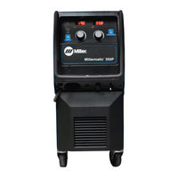
Miller Millermatic 350 MIG Welder
Brand:
Miller
| Category:
Welding System
| Size: 2.59 MB
Table of Contents
Table of Contents
3
Section 1 − Safety Precautions - Read before Using
5
Symbol Usage
5
Arc Welding Hazards
5
Additional Symbols for Installation, Operation, and Maintenance
7
California Proposition 65 Warnings
8
Principal Safety Standards
8
EMF Information
8
Section 2 − Consignes de Sécurité − Lire Avant Utilisation
9
Symboles Utilisés
9
Dangers Relatifs Au Soudage À L'arc
9
Dangers Supplémentaires en Relation Avec L'installation, Le Fonctionnement Et la Maintenance
11
Proposition Californienne 65 Avertissements
12
Principales Normes de Sécurité
13
Informations Relatives Aux CEM
13
Section 3 − Installation
15
Specifications
15
Duty Cycle and Overheating
15
Volt-Ampere Curve
16
Connecting to Weld Output Terminals
16
Installing Work Clamp
17
Installing Welding Gun/Cable Holder
17
Installing Welding Gun
18
Connecting Spoolmatic) 15A or 30A Gun
19
Connecting XR Edge, XR-A Gun, XR-A Python, or XR - Aluma-Pro
20
Setting Gun Polarity for Wire Type
21
Installing Gas Supply
22
Installing Wire Spool and Adjusting Hub Tension
23
Electrical Service Guide
23
Selecting Input Voltage (200/230/460 Volt Models Only)
24
Serial Number and Rating Label Location
25
Selecting a Location and Connecting 3-Phase Input Power
25
Selection a Location and Connecting 1-Phase Input Power
26
Threading Welding Wire for MIG Gun
27
Threading Welding Wire for XR Edge, XR-A Gun, XR-A Python, or XR - Aluma-Pro
28
Threading Welding Wire through XR Guns
29
Section 4 − Operation
30
Controls
30
MIG Mode
30
Jog Mode
30
Weld Status
31
MIG Gun-On-Demand
31
Pulse MIG Mode Voltage Adjustment
31
Pulse MIG Gun-On-Demand
31
Tip Saver
31
Weld Parameters for MIG Mode
32
Weld Parameters for Pulse Mode
33
Section 5 − Programming
34
MIG Welding Mode
34
Pulse MIG Welding Mode
35
Timers
36
Arc Times, Arc Starts, Hot Start (Aluminum Pulse Only), and Crater Fill
37
Setting Hot Start (Aluminum Pulse Only) Parameters
38
Setting Crater Fill
39
Recommended Crater Fill Parameters
40
System Reset
42
Motor Calibration Function
43
Set up Push Motor Torque (SUP)
44
Section 6 − Maintenance &Troubleshooting
45
Routine Maintenance
45
Overheating
45
Measuring Input Capacitor Voltage
46
Changing Drive Roll and Wire Inlet Guide
47
Help Displays
48
Troubleshooting
50
Section 7 − Electrical Diagram
52
Section 8 − Parts List
54
Advertisement
Advertisement
Related Products
Miller Syncrowave 350 LX
Miller Millermatic 350
Miller Continuum 350 and
Miller INVISION 350 MPa AUTO-LINE
Miller XMT Auto-Line 350 CC
Miller XMT Auto-Line 350 CV
Miller Auto-Continuum 350 CE
Miller Big Blue 350X
Miller Syncrowave 351
Miller ProHeat 35 OM-222 166F
Miller Categories
Welding System
Welding Accessories
Camera Accessories
Portable Generator
Motorcycle Accessories
More Miller Manuals
Login
Sign In
OR
Sign in with Facebook
Sign in with Google
Upload manual
Upload from disk
Upload from URL