Sign In
Upload
Manuals
Brands
Miller Manuals
Welding System
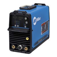
DYNASTY 200 SD
Miller DYNASTY 200 SD Manuals
Manuals and User Guides for Miller DYNASTY 200 SD. We have
3
Miller DYNASTY 200 SD manuals available for free PDF download: Owner's Manual
Miller DYNASTY 200 SD Owner's Manual (96 pages)
Brand:
Miller
| Category:
Welding System
| Size: 3.08 MB
Table of Contents
Table of Contents
3
Section 1 − Safety Precautions - Read before Using
7
Symbol Usage
7
Arc Welding Hazards
7
Additional Symbols for Installation, Operation, and Maintenance
9
California Proposition 65 Warnings
10
Principal Safety Standards
10
EMF Information
10
Section 2 − Consignes de Sécurité − Lire Avant Utilisation
11
Symboles Utilisés
11
Dangers Relatifs au Soudage à L'arc
11
Dangers Supplémentaires en Relation Avec L'installation, le Fonctionnement et la Maintenance
13
Proposition Californienne 65 Avertissements
14
Principales Normes de Sécurité
15
Information EMF
15
SECTION 3 − DEFINITIONS (CE Models)
17
Warning Label Definitions
17
Manufacturer's Rating Label
19
WEEE Label (for Products Sold Within the EU)
19
Symbols and Definitions
20
Section 4 − Installation
21
Specifications
21
DC Volt-Ampere Curves
22
AC Volt-Ampere Curves
23
Duty Cycle and Overheating
24
Selecting a Location
25
Weld Output Terminals and Selecting Cable Sizes
26
Remote 14 Receptacle Information
26
Gas Connections
27
TIG HF Impulse/ Lift-Arct Connections
27
Stick Connections
28
Electrical Service Guide
28
Connecting Three-Phase Input Power
29
Connecting Single-Phase Input Power
30
Section 5 − Operation
31
Controls
31
Encoder Control
32
Amperage Control
32
Ammeter and Parameter Display
32
Voltmeter
33
Polarity Control
33
Lift-Arce and HF TIG Start Procedures
34
Process Control
35
Output Control
35
Pulser Control (DX Models Only)
36
Sequencer Controls (DX and CE Models)
37
Adjust Controls (Preflow/Post Flow/Dig/Purge)
38
AC Waveshape
39
Spot Time Control (Reconfigured RMT 2T HOLD Output Selection)
39
Setting Preflow Time for Use with TIG HF Impulse on Models that Do Not Have a Preflow Control on the Front Panel
40
Factory Parameter Defaults and Range and Resolution
41
Resetting Unit to Factory Default Settings
42
Section 6 − Advanced Functions
44
Programable TIG Start, and Preset Amperage Minimum Parameters
44
AC Waveshape Selection
50
Output Control and Trigger Functions
51
Arc Timer/Counter Display
60
Lockout Functions
61
Setting Unit to Display PPP While Pulse Welding (DX Models Only)
64
Stick Open-Circuit Voltage (OCV) Selection
65
Stick Stuck Check Selection
66
Section 7 − Maintenance and Troubleshooting
67
Routine Maintenance
67
Blowing out Inside of Unit
67
Voltmeter/Ammeter Help Displays
68
Troubleshooting
69
Section 8 − Electrical Diagrams
70
Section 9 − High Frequency (Hf)
71
Welding Processes Requiring High Frequency
71
Correct Installation
71
Section 10 − Setup Guides for (Gtaw) Tig Welding
72
Typical GTAW Set-Ups
72
Section 11 − Selecting and Preparing a Tungsten for DC or Ac Welding with Inverter Machines
74
Selecting Tungsten Electrode (Wear Clean Gloves to Prevent Contamination of Tungsten)
74
Preparing Tungsten Electrode for DC Electrode Negative (DCEN) Welding or AC Welding with Inverter Machines
74
Section 12 − Guidelines for (Gtaw) Tig Welding
75
Positioning the Torch
75
Torch Movement During Welding
76
Positioning Torch Tungsten for Various Weld Joints
76
Section 13 − Setup Guide for (Smaw) Stick Welding
77
Front Panel Display for Stick DCEP (Direct Current Electrode Positive)
77
Section 14 − Guidelines for (Smaw) Stick Welding
78
Electrode and Amperage Selection Chart
78
Stick Welding Procedure
79
Striking an Arc − Scratch Start Technique
79
Striking an Arc − Tapping Technique
79
Positioning Electrode Holder
80
Poor Weld Bead Characteristics
80
Good Weld Bead Characteristics
80
Conditions that Affect Weld Bead Shape
81
Electrode Movement During Welding
81
Butt Joints
82
Lap Joint
82
Tee Joint
82
Weld Test
83
Troubleshooting − Porosity
83
Troubleshooting − Excessive Spatter
83
Troubleshooting − Incomplete Fusion
84
Troubleshooting − Lack of Penetration
84
Troubleshooting − Excessive Penetration
84
Troubleshooting − Burn-Through
85
Troubleshooting − Waviness of Bead
85
Troubleshooting − Distortion
85
Advertisement
Miller DYNASTY 200 SD Owner's Manual (92 pages)
Brand:
Miller
| Category:
Welding System
| Size: 3.21 MB
Table of Contents
Table of Contents
3
Section 1 − Safety Precautions - Read before Using
7
Symbol Usage
7
Arc Welding Hazards
7
Additional Symbols for Installation, Operation, and Maintenance
9
California Proposition 65 Warnings
9
Principal Safety Standards
10
EMF Information
10
Section 2 − Consignes de Sécurité − À Lire Avant Utilisation
11
Signification des Symboles
11
Dangers Relatifs Au Soudage À L'arc
11
Autres Symboles Relatifs À L'installation, Au Fonctionnement Et À L'entretien de L'appareil
13
Principales Normes de Sécurité
14
Information Sur Les Champs Électromagnétiques
14
SECTION 3 − DEFINITIONS (CE Models)
15
Warning Label Definitions
15
Manufacturer's Rating Label
17
Symbols and Definitions
18
Section 4 − Installation
19
Specifications
19
DC Volt-Ampere Curves
20
AC Volt-Ampere Curves
21
Duty Cycle and Overheating
22
Selecting a Location
23
Weld Output Terminals and Selecting Cable Sizes
24
Remote 14 Receptacle Information
24
Gas Connections
25
TIG HF Impulse/ Lift-Arct Connections
25
Stick Connections
26
Electrical Service Guide
26
Connecting Three-Phase Input Power
27
Connecting Single-Phase Input Power
28
Section 5 − Operation
29
Controls
29
Encoder Control
30
Amperage Control
30
Ammeter and Parameter Display
30
Voltmeter
31
Polarity Control (Dynastyt Models Only)
31
Process Control
32
Output Control
32
Pulser Control (DX and LX Models)
33
Sequencer Controls (DX, LX and All CE Models)
34
Adjust Controls (Preflow/Post Flow/Dig/Purge)
35
AC Waveshape (Dynasty Models Only)
36
Spot Time Control (Reconfigured RMT 2T HOLD Output Selection)
36
Memory (Program Storage Locations 1-4) (DX and LX Models if Available)
37
Setting Preflow Time for Use with TIG HF Impulse on Models that Do Not Have a Preflow Control on the Front Panel
38
Factory Parameter Defaults and Range and Resolution
39
Resetting Unit to Factory Default Settings
40
Section 6 − Advanced Functions
41
Programable TIG Start Parameters
41
Output Control and Trigger Functions
44
Arc Timer/Counter Display
54
Lockout Functions
55
Setting Unit to Display PPP While Pulse Welding (DX and LX Models Only)
58
Stick Open-Circuit Voltage (OCV) Selection (All Models)
59
Section 7 − Maintenance and Troubleshooting
60
Routine Maintenance
60
Blowing out Inside of Unit
60
Voltmeter/Ammeter Help Displays
61
Troubleshooting
62
Section 8 − Electrical Diagrams
63
Section 9 − High Frequency (Hf)
64
Welding Processes Requiring High Frequency
64
Correct Installation
64
Section 10 − Selecting and Preparing Tungsten Electrode
65
Selecting Tungsten Electrode
65
Safety Information about Tungsten
65
Preparing Tungsten for AC or DC Electrode Negative (DCEN) Welding
66
Section 11 − Guidelines for Tig Welding (Gtaw)
67
Typical GTAW Set-Ups
67
Positioning the Torch
69
Lift-Arce and HF TIG Start Procedures
70
Torch Movement During Welding
71
Positioning Torch Tungsten for Various Weld Joints
72
Section 12 − Stick Welding (Smaw) Guidelines
73
Front Panel Display for Stick DCEP (Direct Current Electrode Positive)
73
Electrode and Amperage Selection Chart
74
Stick Welding Procedure
75
Striking an Arc − Scratch Start Technique
75
Striking an Arc − Tapping Technique
75
Positioning Electrode Holder
76
Poor Weld Bead Characteristics
76
Good Weld Bead Characteristics
76
Conditions that Affect Weld Bead Shape
77
Electrode Movement During Welding
77
Butt Joints
78
Lap Joint
78
Tee Joint
78
Weld Test
79
Troubleshooting − Porosity
79
Troubleshooting − Excessive Spatter
79
Troubleshooting − Incomplete Fusion
80
Troubleshooting − Lack of Penetration
80
Troubleshooting − Excessive Penetration
80
Troubleshooting − Burn-Through
81
Troubleshooting − Waviness of Bead
81
Troubleshooting − Distortion
81
Section 13 − Parts List
82
Options and Accessories
92
Miller DYNASTY 200 SD Owner's Manual (68 pages)
Brand:
Miller
| Category:
Welding Accessories
| Size: 1.73 MB
Table of Contents
Table of Contents
3
Section 1 − Safety Precautions - Read before Using
7
Symbol Usage
7
Arc Welding Hazards
7
Additional Symbols for Installation, Operation, and Maintenance
9
California Proposition 65 Warnings
10
Principal Safety Standards
10
EMF Information
10
Section 2 − Consignes de Sécurité − Lire Avant Utilisation
11
Symboles Utilisés
11
Dangers Relatifs au Soudage à L'arc
11
Dangers Supplémentaires en Relation Avec L'installation, le Fonctionnement et la Maintenance
13
Proposition Californienne 65 Avertissements
14
Principales Normes de Sécurité
15
Informations Relatives aux CEM
15
SECTION 3 − DEFINITIONS (CE Models)
17
Warning Label Definitions
17
WEEE Label (for Products Sold Within the EU)
18
Symbols and Definitions
19
Section 4 − Installation
20
Important Information Regarding CE Products (Sold Within the EU)
20
Serial Number and Rating Label Location
20
Specifications
21
DC Volt-Ampere Curves
22
AC Volt-Ampere Curves
23
Duty Cycle and Overheating
24
Selecting a Location
25
Weld Output Terminals and Selecting Cable Sizes
26
Remote 14 Receptacle Information
27
Gas Connections
27
TIG HF Impulse/ Lift-Arct Connections
28
Stick Connections
28
Tigrunner Connections
29
Electrical Service Guide
30
Connecting Three-Phase Input Power
31
Connecting Single-Phase Input Power
32
Section 5 − Operation
33
Controls
33
Encoder Control
33
Amperage Control
34
Ammeter and Parameter Display
34
Voltmeter
34
Polarity Control
35
Lift-Arc and HF TIG Start Procedures
35
Process Control
36
Output Control
36
Pulser Control (DX Models Only)
37
Sequencer Controls (DX Models Only)
38
Adjust Controls (Preflow/Post Flow/Dig/Purge)
39
AC Waveshape
40
Factory Parameter Defaults and Range and Resolution
40
Resetting Unit to Factory Default Settings
42
Arc Timer/Counter Display
42
Section 6 − Advanced Functions
43
Accessing Advanced Functions
43
Programmable TIG Start Parameters
44
Output Control and Trigger Functions
48
AC Waveshape Selection
53
Setting Preflow Time
54
Spot Enable
54
Stick Open-Circuit Voltage (OCV) Selection
54
Stick Stuck Check Selection
55
Lockout Functions
55
Setting Unit to Display PPP While Pulse Welding (DX Models Only)
57
External Pulse Control
57
Section 7 − Maintenance and Troubleshooting
58
Routine Maintenance
58
Blowing out Inside of Unit
59
Voltmeter/Ammeter Help Displays
60
Troubleshooting
61
Section 8 − Parts List
61
Recommended Spare Parts
61
Section 9 − Electrical Diagrams
62
Section 10 − High Frequency
63
Welding Processes Requiring High Frequency
63
Installation Showing Possible Sources of HF Interference
63
Recommended Installation to Reduce HF Interference
64
Section 11 − Selecting and Preparing a Tungsten for DC or Ac Welding with Inverter Machines
65
Selecting Tungsten Electrode (Wear Clean Gloves to Prevent Contamination of Tungsten)
65
Preparing Tungsten Electrode for DC Electrode Negative (DCEN) Welding or AC Welding with Inverter Machines
65
Advertisement
Advertisement
Related Products
Miller DYNASTY 200 DX
Miller Dynasty 210
Miller Dynasty 210 DX CPS CE
Miller Dynasty 280 Series
Miller Dynasty 210 CE
Miller DYNASTY 350
Miller Dynasty 400
Miller DYNASTY DX
Miller Dynasty Series 350
Miller Dynasty Series 700
Miller Categories
Welding System
Welding Accessories
Camera Accessories
Portable Generator
Motorcycle Accessories
More Miller Manuals
Login
Sign In
OR
Sign in with Facebook
Sign in with Google
Upload manual
Upload from disk
Upload from URL