Sign In
Upload
Manuals
Brands
Miller Manuals
Welding System
Big Blue 500 X
Miller Big Blue 500 X Manuals
Manuals and User Guides for Miller Big Blue 500 X. We have
4
Miller Big Blue 500 X manuals available for free PDF download: Owner's Manual, Manual
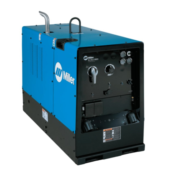
Miller Big Blue 500 X Owner's Manual (96 pages)
Brand:
Miller
| Category:
Welding System
| Size: 3.46 MB
Table of Contents
Table of Contents
3
Section 1 − Safety Precautions − Read before Using
7
Symbol Usage
7
Arc Welding Hazards
7
Engine Hazards
9
Compressed Air Hazards
9
Additional Symbols for Installation, Operation, and Maintenance
10
California Proposition 65 Warnings
12
Principal Safety Standards
12
EMF Information
12
Section 2 − Consignes de Sécurité − Lire Avant Utilisation
13
Signification des Symboles
13
Dangers Relatifs au Soudage à L'arc
13
Dangers Existant en Relation Avec le Moteur
15
Dangers Liés à L'air Comprimé
16
Dangers Supplémentaires en Relation Avec L'installation, le Fonctionnement et la Maintenance
17
Proposition Californienne 65 Avertissements
19
Principales Normes de Sécurité
19
Informations Relatives aux CEM
19
Section 3 − Definitions
20
Additional Safety Symbols and Definitions
20
Miscellaneous Symbols and Definitions
23
Section 4 − Specifications
24
Important Information Regarding CE Products (Sold Within the EU)
24
Weld, Power, and Engine Specifications
24
Environmental Specifications
24
Dimensions, Weights, and Operating Angles
25
Volt-Ampere Curves for CC Models
25
Volt-Ampere Curves for CC/CV Models
26
Fuel Consumption
27
Duty Cycle and Overheating
27
AC Generator Power Curve
28
Optional Three-Phase Generator Curves
28
Section 5 − Installation
29
Serial Number and Rating Label Location
29
Installing Welding Generator
29
Mounting Welding Generator
30
Grounding Generator to Truck or Trailer Frame
31
Using Lifting Eye
31
Installing Exhaust Pipe
32
Connecting the Battery
32
Engine Prestart Checks
33
Connecting to Weld Output Terminals
34
Selecting Weld Cable Sizes
35
Connecting to Remote Amperage Adjust Receptacle RC13 on CC Models
35
Connecting to Remote 14 Receptacle RC14 on CC/CV Models
36
Section 6 − Operating Welding Generator − CC Models
38
Front Panel Controls for CC Models (See Section 6-2)
38
Description of Front Panel Controls for CC Models (See Section 6-1)
39
Remote Amperage Control on CC Models (Optional)
40
Weld Control/Arc Condition Information Label
40
Section 7 − Operating Welding Generator − CC/CV Models
42
Front Panel Controls for CC/CV Models (See Section 7-2)
42
Description of Front Panel Controls for CC/CV Models (See Section 7-1)
43
Process/Contactor Switch on CC/CV Models
44
Remote Voltage/Amperage Control on CC/CV Models (Optional)
45
Fuel/Hour Gauge Descriptions
46
Optional Oil Pan Heater Operation
47
Section 8 − Operating Auxiliary Equipment
48
Domestic Auxiliary Power Receptacles
48
GFCI Receptacle Information, Resetting and Testing
49
Connecting to Optional Three-Phase Generator (CC/CV Models Only)
50
Export Auxiliary Power Receptacles
51
Section 9 − Maintenance & Troubleshooting
52
Maintenance Label
52
Routine Maintenance
53
Checking Generator Brushes
54
Servicing Air Cleaner
55
Inspecting/Cleaning Optional Spark Arrestor
56
Adjusting Engine Speed
57
Servicing Fuel and Lubrication Systems
58
Overload Protection
59
Troubleshooting
60
Section 10 − Electrical Diagrams
64
Section 11 − Run-In Procedure
68
Wetstacking
68
Run-In Procedure Using Load Bank
69
Run-In Procedure Using Resistance Grid
70
Section 12 − Generator Power Guidelines
71
Section 13 − Parts List
78
Advertisement
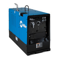
Miller Big Blue 500 X Owner's Manual (80 pages)
Brand:
Miller
| Category:
Welding System
| Size: 2.36 MB
Table of Contents
Table of Contents
3
Section 1 − Safety Precautions − Read before Using
7
Symbol Usage
7
Arc Welding Hazards
7
Engine Hazards
9
Compressed Air Hazards
9
Additional Symbols for Installation, Operation, and Maintenance
10
California Proposition 65 Warnings
12
Principal Safety Standards
12
EMF Information
12
Section 2 − Consignes de Sécurité − Lire Avant Utilisation
13
Signification des Symboles
13
Dangers Relatifs au Soudage à L'arc
13
Dangers Existant en Relation Avec le Moteur
15
Dangers Liés à L'air Comprimé
16
Dangers Supplémentaires en Relation Avec L'installation, le Fonctionnement et la Maintenance
17
Proposition Californienne 65 Avertissements
19
Principales Normes de Sécurité
19
Informations Relatives aux CEM
19
Section 3 − Definitions
21
Additional Safety Symbols and Definitions
21
Miscellaneous Symbols and Definitions
23
Section 4 − Specifications
25
Serial Number and Rating Label Location
25
Weld, Power, and Engine Specifications
25
Dimensions, Weights, and Operating Angles
25
Environmental Specifications
26
Duty Cycle and Overheating
26
Volt-Ampere Curves for CC/CV Models
27
Volt-Ampere Curves for CC Models
28
Fuel Consumption
28
AC Generator Power Curve
29
Optional Three-Phase Generator Curves
29
Section 5 − Installation
30
Installing Welder/Generator
30
Grounding Generator to Truck or Trailer Frame
31
Using Lifting Eye
31
Installing Exhaust Pipe
32
Connecting the Battery
32
Engine Prestart Checks
33
Connecting to Weld Output Terminals
34
Selecting Cable Sizes
35
Connecting to Remote Amperage Adjust Receptacle RC13 on CC Models
35
Connecting to Remote 14 Receptacle RC14 on CC/CV Models
36
Section 6 − Operating Welder/Generator − CC Models
37
Front Panel Controls for CC Models (See Section 6-2)
37
Description of Front Panel Controls for CC Models (See Section 6-1)
38
Remote Amperage Control on CC Models (Optional)
39
Weld Control/Arc Condition Information Label
39
Section 7 − Operating Welder/Generator − CC/CV Models
40
Front Panel Controls for CC/CV Models (See Section 7-2)
40
Description of Front Panel Controls for CC/CV Models (See Section 7-1)
41
Process/Contactor Switch on CC/CV Models
42
Remote Voltage/Amperage Control on CC/CV Models (Optional)
43
Fuel/Hour Gauge Descriptions
44
Optional Oil Pan Heater Operation
45
Section 8 − Operating Auxiliary Equipment
46
Domestic Auxiliary Power Receptacles
46
Connecting to Optional Three-Phase Generator (CC/CV Models Only)
47
Export Auxiliary Power Receptacles
48
GFCI Receptacle Information, Resetting and Testing
49
Section 9 − Maintenance & Troubleshooting
50
Maintenance Label
50
Routine Maintenance
51
Checking Generator Brushes
52
Servicing Air Cleaner
53
Inspecting/Cleaning Optional Spark Arrestor
54
Battery Maintenance
54
Adjusting Engine Speed
55
Servicing Fuel and Lubrication Systems
56
Overload Protection
57
Troubleshooting
58
Section 10 − Parts List
62
Recommended Spare Parts
62
Section 11 − Electrical Diagrams
64
Section 12 − Run-In Procedure
68
Wetstacking
68
Run-In Procedure Using Load Bank or Resistance Grid
69
Section 13 − Generator Power Guidelines
70
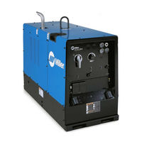
Miller Big Blue 500 X Owner's Manual (72 pages)
Engine Driven Welder/Generator
Brand:
Miller
| Category:
Welding System
| Size: 2.23 MB
Table of Contents
Table of Contents
3
Section 1 − Safety Precautions − Read before Using
5
Symbol Usage
5
Arc Welding Hazards
5
Engine Hazards
7
Compressed Air Hazards
7
Additional Symbols for Installation, Operation, and Maintenance
8
California Proposition 65 Warnings
10
Principal Safety Standards
10
EMF Information
10
Section 2 − Consignes de Sécurité − Lire Avant Utilisation
11
Signification des Symboles
11
Dangers Relatifs Au Soudage À L'arc
11
Dangers Existant en Relation Avec Le Moteur
13
Dangers Liés À L'air Comprimé
14
Dangers Supplémentaires en Relation Avec L'installation, Le Fonctionnement Et la Maintenance
15
Proposition Californienne 65 Avertissements
17
Principales Normes de Sécurité
17
Informations Relatives Aux CEM
17
Section 3 − Definitions
18
Additional Safety Symbols and Definitions
18
Miscellaneous Symbols and Definitions
19
Section 4 − Specifications
20
Serial Number and Rating Label Location
20
Weld, Power, and Engine Specifications
20
Dimensions, Weights, and Operating Angles
20
Environmental Specifications
20
Duty Cycle and Overheating
21
Volt-Ampere Curves for CC Models
21
Volt-Ampere Curves for CC/CV Models
22
Fuel Consumption
23
AC Generator Power Curve
23
Optional Three-Phase Generator Curves
24
Section 5 − Installation
25
Installing Welder/Generator
25
Grounding Generator to Truck or Trailer Frame
26
Using Lifting Eye
26
Installing Exhaust Pipe
27
Connecting the Battery
27
Engine Prestart Checks
28
Weld Output Terminals
29
Connecting Weld Output Cables
29
Selecting Weld Cable Sizes
30
Connecting to Remote Amperage Adjust Receptacle RC13 on CC Models
30
Connecting to Remote 14 Receptacle RC14 on CC/CV Models
31
Section 6 − Operating Welder/Generator − CC Models
32
Front Panel Controls for CC Models (See Section 6-2)
32
Description of Front Panel Controls for CC Models (See Section 6-1)
33
Remote Amperage Control on CC Models (Optional)
34
Weld Control/Arc Condition Information Label
34
Section 7 − Operating Welder/Generator − CC/CV Models
36
Front Panel Controls for CC/CV Models (See Section 7-2)
36
Description of Front Panel Controls for CC/CV Models (See Section 7-1)
37
Process/Contactor Switch on CC/CV Models
38
Remote Voltage/Amperage Control on CC/CV Models (Optional)
39
Fuel/Hour Gauge Descriptions
40
Section 8 − Operating Auxiliary Equipment
41
Domestic Auxiliary Power Receptacles
41
Connecting to Optional Three-Phase Generator (CC/CV Models Only)
42
Export Auxiliary Power Receptacles
43
GFCI Receptacle Information, Resetting and Testing
44
Section 9 − Maintenance & Troubleshooting
45
Maintenance Label
45
Routine Maintenance
46
Operating Optional Oil Pan Heater
47
Checking Generator Brushes
47
Servicing Air Cleaner
48
Battery Maintenance
48
Inspecting and Cleaning Optional Spark Arrestor Muffler
49
Maintaining Stainless Steel (Models with Optional Package)
49
Adjusting Engine Speed
50
Servicing Fuel and Lubrication Systems
51
Overload Protection
52
Troubleshooting
53
Section 10 − Parts List
57
Recommended Spare Parts
57
Section 11 − Electrical Diagrams
58
Section 12 − Run-In Procedure
62
Wetstacking
62
Run-In Procedure Using Load Bank or Resistance Grid
63
Section 13 − Generator Power Guidelines
64
Grounding When Supplying Building Systems
65
Advertisement
Miller Big Blue 500 X Manual (9 pages)
Diesel Engine-Driven Welder/Generator
Brand:
Miller
| Category:
Portable Generator
| Size: 1.38 MB
Table of Contents
Specifications
2
Control Panel
2
Performance Data
3
Engine Specifications
4
Mounting Specifications
6
Typical Installations
7
Ordering Information
8
Advertisement
Related Products
Miller Big Blue 500 Pro
Miller Big Blue 300 PRO Series
Miller Big Blue 400 CX CE
Miller Big Blue 300 P
Miller Big Blue 450 Duo CST
Miller Big Blue 300 D
Miller Big Blue 600 Pro
Miller Big Blue 400 PipePro
Miller Big Blue 400 PX CE
Miller Big Blue 350 PipePro
Miller Categories
Welding System
Welding Accessories
Camera Accessories
Portable Generator
Motorcycle Accessories
More Miller Manuals
Login
Sign In
OR
Sign in with Facebook
Sign in with Google
Upload manual
Upload from disk
Upload from URL