Sign In
Upload
Manuals
Brands
Miller Manuals
Welding System
Auto-Continuum 500
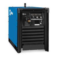
Miller Auto-Continuum 500 Manuals
Manuals and User Guides for Miller Auto-Continuum 500. We have
2
Miller Auto-Continuum 500 manuals available for free PDF download: Owner's Manual
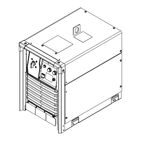
Miller Auto-Continuum 500 Owner's Manual (92 pages)
Brand:
Miller
| Category:
Welding System
| Size: 4.12 MB
Table of Contents
Table of Contents
3
Section 1 − Safety Precautions - Read before Using
7
Symbol Usage
7
Arc Welding Hazards
7
Additional Symbols for Installation, Operation, and Maintenance
9
California Proposition 65 Warnings
10
Principal Safety Standards
10
EMF Information
10
Section 2 − Consignes de Sécurité − Lire Avant Utilisation
11
Symboles Utilisés
11
Dangers Relatifs au Soudage à L'arc
11
Dangers Supplémentaires en Relation Avec L'installation, le Fonctionnement et la Maintenance
13
Proposition Californienne 65 Avertissements
14
Principales Normes de Sécurité
14
Informations Relatives aux CEM
14
Section 3 − Definitions
15
Additional Safety Symbols and Definitions
15
Miscellaneous Symbols and Definitions
17
Section 4 − Specifications
18
Serial Number and Rating Label Location
18
Software Licensing Agreement
18
350 Model Specifications
18
Dimensions and Weight
19
Static Characteristics
19
Environmental Specifications
19
Duty Cycle and Overheating
21
Section 5 − Installation
22
Selecting a Location
22
Weld Output Terminals and Selecting Cable Sizes
23
Connecting Weld Output Cables
24
Remote 10 Wire Feeder Control Receptacle RC2 Information
25
Volt Sense Receptacle RC3 Information
25
Peripheral Receptacle RC22 Functions
26
Devicenet Receptacle
26
Supplementary Protector CB1, Communication Panel, and E-Stop
27
Electrical Service Guide
28
Connecting 3-Phase Input Power
29
Section 6 − Recommended Set-Up Procedures
31
Welding Circuit
31
Arranging Welding Cables to Reduce Welding Circuit Inductance
32
Using Multiple Welding Power Sources
33
Voltage Sensing Lead and Work Cable Connections for Multiple Welding Arcs
34
Earth Grounding
37
Points of Mechanics in MIG Welding
39
Arc Blow
40
Basic Welding Troubleshooting
41
Section 7 − Operation
44
Operator Controls
44
User Interface
45
Description of Front Panel Controls (See Section 7-2)
46
Section 8 − Configuration
47
Accessing Configuration Web
47
Home Screen
47
Setup Screen
48
Setup Screen
49
Arc Management Screen
50
Data Management Screen
51
Help Screen
51
Section 9 − Maintenance & Troubleshooting
52
Routine Maintenance
52
Blowing out Inside of Unit
52
Error Code Troubleshooting Description and Tables
53
Error Code Troubleshooting Description and Tables
54
Troubleshooting
57
SECTION 10 − INSIGHT Coret INSTALLATION
59
License Agreement
59
Downloading Connectivity Survey
59
Obtaining System IP Address
59
Enabling Insight Core through the Continuum's Web
60
Configuring the Network Connection
62
Verifying Network Connection
67
Determining Device Serial Number and License Key
68
Registering Initial Device and Creating an Account
70
Registering Additional Devices
71
Section 11 − Electrical Diagrams
72
Section 12 − Parts List for 350 and 500 Models
80
Advertisement
Miller Auto-Continuum 500 Owner's Manual (76 pages)
with Insight Core
Brand:
Miller
| Category:
Welding System
| Size: 3.27 MB
Table of Contents
Table of Contents
3
Section 1 − Safety Precautions - Read before Using
5
Symbol Usage
5
Arc Welding Hazards
5
Additional Symbols for Installation, Operation, and Maintenance
7
California Proposition 65 Warnings
8
Principal Safety Standards
8
EMF Information
8
Section 2 − Consignes de Sécurité − Lire Avant Utilisation
9
Symboles Utilisés
9
Dangers Relatifs Au Soudage À L'arc
9
Dangers Supplémentaires en Relation Avec L'installation, Le Fonctionnement Et la Maintenance
11
Proposition Californienne 65 Avertissements
12
Principales Normes de Sécurité
12
Informations Relatives Aux CEM
12
Section 3 − Definitions
13
Additional Safety Symbols and Definitions
13
Miscellaneous Symbols and Definitions
15
Section 4 − Specifications
16
Serial Number and Rating Label Location
16
350 Model Specifications
16
Dimensions and Weight
17
Environmental Specifications
17
Static Characteristics
17
Duty Cycle and Overheating
18
Section 5 − Installation
19
Selecting a Location
19
Weld Output Terminals and Selecting Cable Sizes
20
Connecting Weld Output Cables
21
Remote 10 Wire Feeder Control Receptacle RC2 Information
22
Volt Sense Receptacle RC3 Information
22
Peripheral Receptacle RC22 Functions
23
Supplementary Protector CB1, Communication Panel, and E-Stop
23
Aux Power and CB2 (Optional)
24
Devicenet Receptacle
24
Electrical Service Guide
25
Connecting 3-Phase Input Power
26
Section 6 − Recommended Setup Procedures
28
Welding Circuit
28
Arranging Welding Cables to Reduce Welding Circuit Inductance
29
Using Multiple Welding Power Sources
30
Voltage Sensing Lead and Work Cable Connections for Multiple Welding Arcs
31
Earth Grounding
34
Points of Mechanics in MIG Welding
36
Arc Blow
37
Basic Welding Troubleshooting
38
Section 7 − Operation
41
Operator Controls
41
User Interface
42
Description of Front Panel Controls (See Section 7-2)
43
Section 8 − Configuration
44
Accessing Configuration Web
44
Home Screen
44
Setup Screen
45
Arc Management Screen
46
Data Management Screen
47
Help Screen
47
Section 9 − Maintenance & Troubleshooting
48
Routine Maintenance
48
Blowing out Inside of Unit
48
Error Code Troubleshooting Description and Tables
49
Troubleshooting
53
Section 10 − Electrical Diagrams
54
Section 11 − Parts List for 350 and 500 Models
62
Advertisement
Related Products
Miller Auto-Continuum 350
Miller Auto-Continuum Drive CE
Miller Auto Continuum Drive Left CE
Miller Auto Continuum Drive Right CE
Miller Auto Invision II
Miller Auto-Axcess E Digital
Miller Auto Arc
Miller Augmented Arc
Miller Auto Arc Micro-Pulse 2000
Miller AlumaPower 350 MPa Auto-Line CE
Miller Categories
Welding System
Welding Accessories
Camera Accessories
Portable Generator
Motorcycle Accessories
More Miller Manuals
Login
Sign In
OR
Sign in with Facebook
Sign in with Google
Upload manual
Upload from disk
Upload from URL